| Capacitors, Magnetic Circuits, and Transformers is a free introductory textbook on the physics of capacitors, coils, and transformers. See the editorial for more information.... |

|
Home  Energy Mechanical And Electrical Analogies Energy Mechanical And Electrical Analogies |
|||||||||||
| See also: Capacitance | |||||||||||


|
  |
||||||||||
Mechanical and Electrical Analogies
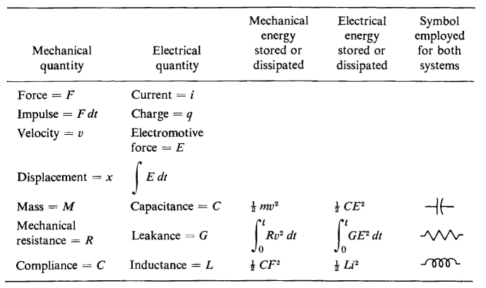
The behavior of the analogous mechanical and electrical systems is defined by the same types of differential equations as is evident from a comparison of Eq. 1-29 with Eq. 1-26 and of Eq. 1-57 with Eq. 1-72. Analogies based on these types of differential equations are shown in Table 1-1.(1) The force F and the voltage or electromotive force E, in Table 1-1 may be constants as well as functions of time. It should be noted that both V and E serve as symbols for voltage.
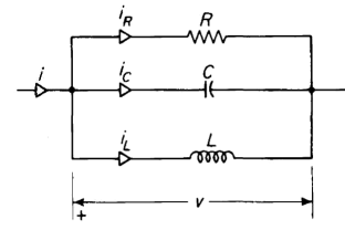
The term compliance is used in connection with the mechanical quantities listed in Table 1-1. Compliance denotes the inverse of stiffness and corresponds to capacitance in the electrical circuit when force in the mechanical system is considered analogous to voltage in the electrical system. The relation shown in Table 1-1 is sometimes called the direct relation. The inverse of these relations may also be used. These follow from comparing a parallel electrical circuit, as shown in Fig. 1-15, with the mechanical system. The differential equation for this parallel circuit is
The inverse relation between mechanical and electrical quantities are shown in Table 1-2. TABLE 1-2. INVERSE RELATION BETWEEN MECHANICAL AND ELECTRICAL QUANTITIES
A comparison of quantities for the torsional system is shown in Table 1-3.
|
|||||||||||
| Home Energy Mechanical And Electrical Analogies |
|
||||||||||


Last Update: 2011-01-09