| Capacitors, Magnetic Circuits, and Transformers is a free introductory textbook on the physics of capacitors, coils, and transformers. See the editorial for more information.... |

|
Home  Magnetic Circuits Magnetic Circuits in Series and in Parallel Magnetic Circuits Magnetic Circuits in Series and in Parallel |
|||||||||||||||||


|
  |
||||||||||||||||
Magnetic Circuits in Series and in Parallel
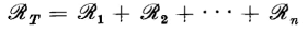
Although the magnetic circuit is similar in many aspects to the electric circuit, calculations of magnetic circuits are generally more complex because of magnetic leakage and because of the nonlinearity of magnetic materials. Equation 3-43 expresses the relation between the magnetic flux and the mmf in a magnetic circuit of uniform cross section A and length l. In that equation the quantity μA/l is known as the permeance P, which is the reciprocal of the reluctance R. If we had a single magnetic circuit with n components in series for which the reluctances would be
we could get the total reluctance simply as follows, provided that there is no leakage
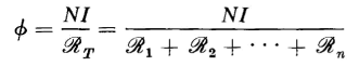
If the total mmf is Nl then the flux in such a circuit is found to be
However, since the values of the various permeabilities μ1, μ2.....,μn depend upon the degree of magnetization, which is generally different for a given value of Φ since the n components that the relationship suggested in Eqs. 3-113 and 3-114 are not particularly useful. It is, therefore, generally more convenient to compute the mmfs for each component for a given value of flux Φ on the basis of the magnetization curve for that component. However, in the cases of magnetic circuits that have air gaps in series and in which the iron is unsaturated so that its reluctance is small in comparison with that of the air gaps, useful approximations can be made by computing the reluctance of each of the air gaps and taking their sum as the total reluctance.
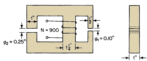
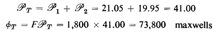
The reasoning that applies to the series magnetic circuit also holds for the parallel magnetic circuit and for rigorous calculations the fluxes in the various parallel branches are computed for a given value of mmf using the magnetization curves. Again if the iron is unsaturated and there are air gaps in parallel of such lengths that the reluctance of the iron is negligible the permeance, which is the reciprocal of reluctance, of the magnetic circuit is the sum of the permeances of the various air gaps provided that leakage is negligible. When the leakage is appreciable the permeance of the leakage paths must be added to those of the air gaps to obtain the total permeance.
|
|||||||||||||||||
| Home Magnetic Circuits Magnetic Circuits in Series and in Parallel |
|
||||||||||||||||


Last Update: 2011-02-16