| 3-1 |
Given a long straight cylindrical conductor of radius a m, in free space, carrying a constant current I distributed uniformly over its cross section. Plot the magnetic field intensity H vs distance from the center of the conductor in terms of the current I for values of distance varying between 0 and 4a. Assume there are no magnetic fields other than the one produced by the conductor in this problem.
|
| 3-2 |
Figure 3-44 shows a cross-sectional view of a straight cylindrical conductor of radius a m carrying a constant current of I amp distributed uniformly over its cross section. Assume the conductor to be in free space.
(a) Determine the value of the line integral of the magnetic field intensity H taken (1) around the triangular path 1 and (2) around the circular path 2.
(b) How would the values of part (a) above be affected if the current I in the conductor remained unchanged but the conductor were surrounded by, and electrically insulated from, a medium having a relative magnetic permeability of μr?
(c) Another identical conductor runs parallel to the conductor in Fig. 3-44, the spacing being 5a between centers. The second conductor carries a current of 10a. Repeat part (a) if the current in the conductors is flowing (1) in the same direction (2) in opposite directions.
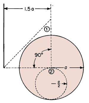 |
| Figure 3-44. Cross section of a cylindrical conductor for Problem 3-2. |
|
| 3-3 |
A magnetic circuit linking a winding of two coils having N1 and N2 turns respectively is shown in Fig. 3-45. The two coils are connected in series aiding, i.e., the direction of the current in each coil is such as to produce flux in the same direction around the core. The current in both coils is I amp.
(a) Determine the value of the line integral of the magnetic field intensity H taken around paths 1, 2, 3, 4, and 5 in Fig. 3-45.
(b) Repeat part (a) above but with the polarity of the lower coil (the one with N2 turns) reversed.
 |
| Figure 3-45. Magnetic core with a winding of 2 coils for Problem 3-3.
|
|
| 3-4 |
A toroid as shown in Fig. 3-9 has a ratio of R2/R1 = 1.5 and has a uniform magnetic permeability throughout. Determine the percent error in using Eq. 3-42(a) instead of 3-42 to determine the flux in the core.
|
| 3-5 |
(a) Determine the current in the exciting winding of the magnetic circuit shown in Fig. 3-16 when the flux in the core is 19,000 maxwells. The core is comprised of U.S.S. Transformer 72, 29 Gage Steel. Stacking factor = 0.95.
(b) What is the ratio of this value of current to the one in Example 3-1 for the same magnetic structure ?
(c) How does this ratio compare with the corresponding ratio of fluxes ?
|
| 3-6 |
The three-legged core in Fig. 3-17 is stacked to a depth of 1.50 in. The laminations are of 0.0140-in. U.S.S. Electrical Sheet Steel. Use Fig. 3-11 to determine the flux in the center leg and in the outer legs for a current of
(a) 10.0 amp.
(b) 3.0 amp. Assume a stacking factor of 0.90.
|
| 3-7 |
Plot in rectangular coordinates on the same graph curves of flux vs ampere turns for the magnetic circuit of Fig, 3-19, using the curve in Fig. 3-11 if the iron is U.S.S. Electrical Sheet Steel, for
(a) The iron alone.
(b) The air gap alone for g =0.100 in.
(c) The combination of iron and air for g =0.100 in. for values of flux up to 25,000 lines using the circuit of Fig. 3-19 and assuming a stacking factor of 0.90. Correct for fringing but neglect leakage.
|
| 3-8 |
(a) In Problem 3-7 what is the mmf when the flux is 12,500 lines, required by
(i) The iron?
(ii) The air gap ?
(iii) The entire magnetic circuit ?
(b) If the permeability of the iron were doubled for the conditions above at 12,500 lines, what would be the mmf required by
(i) The iron?
(ii) The air gap ?
(iii) The entire magnetic circuit ?
|
| 3-9 |
Determine the mmf for a flux of 10,000 maxwells in the core of Fig. 3-19 for an air gap 0.100 in. long. Neglect leakage flux, but correct for fringing.
|
| 3-10 |
Using the graphical construction shown in Fig. 3-22 determine the values of flux in the magnetic structure of Example 3-4 and Fig. 3-19 for the following values of mmf: 200, 400, 600, 800, and 1,200 amp turns. Plot, in rectangular coordinates, these values of flux for the various mmfs above.
|
| 3-11 |
Determine the flux in the magnetic structure of Problem 3-10 if the air gap has a length of 0.100 in. and the current in the 600-turn exciting winding is 2.5 amp.
|
| 3-12 |
The core of a large 60-cycle power transformer weighs 100 tons. The core material is comprised of 4.25 percent silicon steel laminations 0.014 in. thick. The specific weight of the core material is 465 lb per cu ft. The magnetic characteristics of this material are shown graphically in Fig. 3-11. Determine:
(a) The energy stored magnetically in a cubic inch of the core when the flux density is 80 kilolines per sq in. (Assume a linear relationship between B and H.)
(b) The energy stored in the entire core when the flux density is 80 kilolines per sq in.
(c) The energy in joules per kilogram for a flux density of 80 kilolines per sq in.
|
| 3-13 |
If the permeance, i.e., the ratio of flux to mmf, of the core in Problem 3-12 above were reduced 20 percent, what would be the energy stored in the entire magnetic circuit when the flux density is 80 kilolines per sq in. ? (Assume a linear relationship between B and H.)
|
| 3-14 |
The electromagnet in Fig. 3-46 is made up of laminations stacked to a height of 1 in. The winding consists of 8,000 turns of No. 28 enamel wire. Neglect the reluctance of the iron, the effect of leakage, and fringing and determine the current required to develop a force of 37.5 lb when
(a) The air gap length is 0.05 in.
(b) The air gap length is 0.10 in.
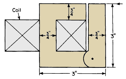 |
| Figure 3-46. Electromagnet for Problem 3-14. |
|
| 3-15 |
In Problem 3-14 how much energy is stored in the air gap when its length is
0.10 in. and the force is 37.5 lb?
|
| 3-16 |
Figure 3-47 shows an Alnico V permanent magnet with soft iron pole shoes and an air gap g. The demagnetization curve for this material is given below.
|
H oersteds
|
0
|
100
|
200
|
300
|
400
|
500
|
550
|
600
|
|
B kilogauss
|
12.5
|
12.3
|
12.0
|
11.5
|
10.7
|
8.8
|
6.6
|
0
|
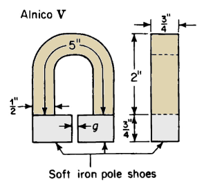 |
| Figure 3-47. Alnico magnet with soft iron pole shoes and air gap for Problem 3-16. |
Plot a demagnetization curve similar to that shown in Fig. 3-31 (a) and determine the flux for an air gap length.
(a) g =0.125 in.
(b) g = 0.250 in.
(c) g = 0.060 in.
Neglect leakage but correct for fringing at the air gap.
|
| 3-17 |
If the reluctance of the iron can be neglected and the alnico in the magnet of Problem 3-16 were to be replaced by silicon steel with negligible residual flux, how many ampere turns would need to be furnished to produce the same values of flux in the respective air gaps of Problem 3-16?
|
| 3-18 |
A permanent magnet-moving coil instrument has a magnetic circuit similar in configuration to that shown in Fig. 3-27. The volume of the double air gap (the two air gaps in series) is 0.24 cu in. The magnet flux in the structure is furnished by an alnico magnet that has the demagnetization characteristic shown in Fig. 3-31 (a). Neglect leakage, fringing, and the reluctance of the soft iron portions and determine the smallest volume of alnico that will furnish the air gap with a flux density of 70 kilolines per sq in.
|
| 3-19 |
The rotor of a 2-pole permanent-magnet generator consists of Alnico V material and has an effective length of 1.00 in. (see Fig. 3-35(b) for rotor shape). The effective cross-sectional area is 1/8 sq in. (1/4 x 1/2). The minimum double air gap has an equivalent length of 0.020 in. and a maximum equivalent gap length of 0.065 in. The characteristic of the Alnico V material is listed in the table of Problem 3-16. Determine
(a) The flux when the rotor position is such that the air gap is a maximum.
(b) The flux when the rotor position is such that the air gap is minimum after having occupied a position of maximum air gap.
|
| 3-20 |
The following data define the upper half of the hysteresis loop for a sample of U.S.S. Transformer 72, 29 Gage Steel.
B
Kilolines
per square inch
|
0 |
10 |
20 |
30 |
40 |
45 |
50 |
55 |
60 |
64.3 |
H
ampere turns
per inch
|
0.85 |
1.00 |
1.17 |
1.45 |
1.87 |
2.14 |
2.50 |
2.97 |
3.65 |
4.45 |
B
Kilolines
per square inch
|
60 |
55 |
50 |
45 |
40 |
30 |
20 |
10 |
0 |
H
ampere turns
per inch
|
2.65 |
1.47 |
0.80 |
0.37 |
0.05 |
-0.35 |
-0.60 |
-0.73 |
-0.85 |
Plot the complete hysteresis loop and determine
(a) The residual flux density in (i) Kilolines per square inch, (ii) Gausses.
(b) The coercive force in
(i) Ampere turns per inch, (ii) Oersteds.
(c) The energy product in joules for a flux density of B = +24 kilolines per square inch on the decreasing portion of the loop.
|
| 3-21 |
On the basis of the hysteresis loop of Problem 3-20 determine the hysteresis loss in joules per cycle per cubic inch of iron at a maximum flux density of 64.3 kilolines per sq in.
|
| 3-22 |
A transformer core has a mean length of 50 in. and a uniform gross cross-sectional area of 20 sq in. The core material is the same as that of Problem 3-20.
(a) Determine the hysteresis loss in watts for a frequency of 60 cps and a maximum flux density of 64.3 kilolines per sq in. The stacking factor is 0.90.
(b) What is the hysteresis loss in watts per pound if the density is 0.272 lb per cu in. ?
|
| 3-23 |
The thickness of 29 gage sheets is 0.0140 in. and the resistivity of the core material in Problem 3-22 is 22 microhms per cu in. Determine the eddy-current loss in the core of Problem 3-22 for a frequency of 60 cps and a maximum flux density of 64.3 kilolines per sq in.
|
| 3-24 |
Determine the total core loss for a transformer core of Problem 3-22 if the flux density is 64.3 kilolines per sq in. and the frequency is 120 cps.
|
| 3-25 |
Assume the hysteresis loss in the core of Problem 3-22 to vary in accordance with the equation
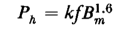
and determine the total core loss for a frequency of 60 cps and a flux density of 90,000 maxwells per sq in.
|
| 3-26 |
The core loss in an iron-core reactor is 548 w of which 402 w is hysteresis loss when the applied voltage is 240 v and the frequency is 30 cps. What is the core loss when the voltage and the frequency are both doubled? Neglect the resistance of the winding.
|
| 3-27 |
The core loss in a transformer is 500 w of which 100 w is eddy-current loss. If the number of turns in the exciting winding were to remain unchanged but the volume of the core were doubled by increasing the cross-section of the iron, what would be the core loss for the same applied voltage and frequency ? Neglect winding resistance and assume
for a given volume.
|
| 3-28 |
The dimensions of the core in a core-type transformer are as follows: the outside dimensions of the core parallel to the plane of the window are 8 3/4 in. x 10 in.; cross section of iron = 2 5/8 in. x 4 1/2 in. The laminations are 26 (t = 0.0185 in.) gage and are stacked to a depth of 4 1/2 in. with a stacking factor of 0.93. The primary winding has two coils of 87 turns each. The rated primary voltage when the two coils are connected in series is 440 v at 60 cps. The density of the iron is 0.272 lb per cu in. The following no-load tests were made by energizing the primary winding.
|
Volts
|
Frequency
|
Watts
|
|
440
|
60
|
103.5
|
|
220
|
30
|
45.2
|
Determine
(a) The 60-cycle hysteresis loss at rated voltage and rated frequency.
(b) The 60-cycle eddy-current loss at rated voltage and rated frequency.
(c) The core loss per pound at rated voltage and rated frequency.
(d) The core loss per pound if the same iron were used but if the laminations were 24 gage (T = 0.0250 in.).
|
| 3-29 |
Determine the magnetic flux in each of the three legs of the electromagnet shown in Fig. 3-43 if the air gaps in the outer legs are as indicated and an air gap of 0.05 in. is inserted in the middle leg and when the current in the 900-turn winding is 3.5 amp. Neglect the reluctance of the iron, and magnetic leakage but correct for fringing.
|
| 3-30 |
Determine the forces on each of the faces of the air gaps in the electromagnet of Problem 3-29.
|

 Magnetic Circuits


