| 4-1 |
A toroid consists of a wooden core with a winding having two layers with 500 uniformly distributed turns each. The inside and outside radii of the core are 5 and 6 in. respectively, and the axial depth of the core is 4 in. Assume all the magnetic flux to be confined to the wooden core, and the mean length of the flux path to be the average of the inner and outer circumferences of the core.
(a) If the two layers of the windings are connected in series with their polarities such that the mmfs add and the current is 1 amp, determine
(i) The magnetic flux in the core,
(ii) The flux linkage,
(iii) The self-inductance of the winding,
(iv) The energy stored in the magnetic field.
(b) Repeat part (a) above if a current of 1 amp is passed through only one layer of the winding.
(c) Repeat part (b) above if the two layers are connected in parallel with the polarities such that the mmfs add and if the total current is 2 amp.
(d) Repeat part (a) for a core having a uniform relative permeability μr = 400.
|
| 4-2 |
Determine the magnetic reluctance and the magnetic permeance of the toroid for the conditions specified in Problem 4-1 (a), (b), (c), and (d).
|
| 4-3 |
A long, straight, round copper conductor of radius R m and length l m carries a current of I amp distributed uniformly over its cross section. Determine in terms of I and other suitable constants on the basis that the relative permeability of copper μr = 1
(a) The total magnetic flux within the conductor.
(b) The magnetic energy density within the conductor as function of the distance from the center of the conductor.
|
| 4-4 |
The number of turns in the windings designated as circuits 1 and 2 in Fig. 4-4(b) is N1 = 100 and N2 = 200. A current i1 = 5 amp in circuit 1 produces an equivalent flux μ11 = 0,0032 weber, which links all N1 turns. Assume the magnetic circuit to be linear, i.e., the reluctance of the iron represented by the shaded area to be negligible. Calculate
(a) The self-inductance L11 of circuit 1.
(b) The mutual flux Φ21 if the reluctances are in the ratios R2/R1 = 2 and R1/R1 = 2/3
(c) The mutual inductance L21 between the two circuits.
(d) The coefficients k1, k2 and the coefficient of coupling k.
(e) The self-inductance L22 of circuit 2.
(f) The energy stored in the fields associated with each of the three reluctances.
(g) The stored energy based on 1/2L11i12 [How does this compare with the sum of the three values of part (f)?]
|
| 4-5 |
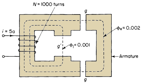
Figure 4-9 shows an electromagnet with equal variable air gaps g. When the current in the 1000-turn winding on the stationary member is 5 amp the flux through the movable member is Φa = 0.002 weber and the leakage flux Φ1 = 0.001 weber. The reluctance of the iron is negligible. The length of the variable air gaps g is increased 10 percent; the flux Φa through these air gaps is held constant at 0.002 weber. Neglect the effect of fringing.
 |
| Figure 4-9. Electromagnet for Problem 4-5 |
(a) Calculate for the increased length of air gaps
(i) The current.
(ii) The leakage flux Φ1.
(iii) The total energy stored in the field of the two air gaps g.
(iv) The stored energy associated with the leakage flux Φ1.
(v) The self-inductance of the 200-turn winding,
(vi) The energy stored in the self-inductance (1/2Li2).
(b) Calculate
(i) The mechanical energy input or output. (Which is it?)
(ii) The electromagnetic energy input or output (Which is it?) during the increase in the length of the air gaps.
(c) If the original length of each of the gaps^ is 0.125 in., calculate the force.
(d) Neglect fringing and calculate the flux density in the air gaps g.
(e) Calculate the force on the basis of area and flux density and compare with that of part (c).
HINT : Use Eq. 3-71.
(f) Calculate the average voltage induced in the winding if the time during which the air gap is increased is 0.01 sec.
|
| 4-6 |
When each of the variable air gaps^ in Fig. 4-9 has a length of 0.125 in. and the current in the 1,000-turn winding is 5 amp, the fluxes Φa and Φ1 are 0.002 and 0.001 weber, respectively. The length of air gap g' is assumed to be fixed. Neglect fringing and the reluctance of the iron and calculate
(a) The length and the cross-sectional area of the fixed air gap g' if the cross-sectional areas of all three air gaps are equal.
(b) The permeance of the fixed air gap g'.
(c) The permeance of the two variable air gaps g in series as a function of the length of a single gap.
(d) The total permeance of the magnetic circuit as a function of the length of a single air gap g.
(e) The self-inductance of the 1,000-turn winding as a function of the length of a single air gap g.
(f) The total force on the movable member or armature based on the relationship
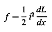
for a current of 5 amp when the length of each air gap g is 0.125 in.
(g) The force on the faces of the fixed air gap g' for the conditions of part (f).
|
| 4-7 |
The self-inductance of two identical parallel straight nonmagnetic cylinders is given by
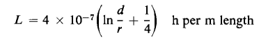
where d is the distance between centers (small in comparison with the length of the conductors), and where r is the radius of each conductor. During a short circuit on a power system, the current in two such conductors reaches a peak value of 100,000 amp. Calculate the force per meter length on each conductor if the radius of each conductor is 1 in. and the spacing is 6 in. between centers.
|
| 4-8 |
Figure 4-10 shows a rotary electromagnet.
(a) Neglect the reluctance of the iron, leakage, and fringing and determine for the rotor position in Fig. 4-10(a) when the current in the stator
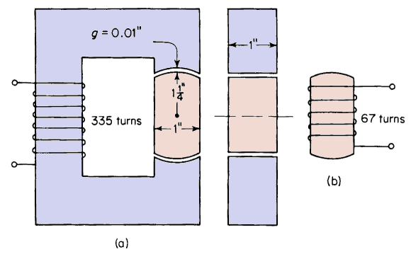 |
| Figure 4-10. (a) Rotary electromagnet winding on stator only, for Problem 4-8, (b) rotor of rotary electromagnet with winding for Problems 4-9 and 4-10.
|
winding is 1.5 amp
(i) The flux in the air gap.
(ii) The flux in the iron.
(iii) The self-inductance of the stator.
(iv) The permeance of the magnetic circuit.
(v) The reluctance of the magnetic circuit.
(vi) The energy stored in the air gap.
(vii) The energy stored in the iron.
(b) Repeat part (a) above, but with the rotor displaced 15°
(i) In the clockwise direction,
(ii) In the counterclockwise direction.
(c) What is the torque in both parts of (b) above?
(d) Repeat part (a) above when the rotor is in the position shown in Fig. 4-10(a), taking into account the reluctance of the iron (USS Electrical Annealed Sheet Steel) if the mean length of the path in the iron is 8.5 in. Use Fig. 3-12 for determining the effect of the iron.
|
| 4-9 |
Suppose that a winding of 67 turns were placed on the rotor [see Fig. 4-10(b)] of the electromagnet in Problem 4-8 and a current of 7.5 amp passed through this winding while the current in the stator winding was zero. Neglect leakage and fringing, but take into account the reluctance of the iron, and determine
(a) The flux in the air gap.
(b) The flux linkages of the rotor winding.
(c) The self-inductance of the rotor on the basis of Eq. 4-6.
(d) The permeance of the magnetic circuit.
(e) The flux linking the stator winding.
(f) The flux linkage of the stator winding due to the current in the rotor winding.
(g) The mutual inductance between stator and rotor on the basis of flux linkage per ampere.
|
| 4-10 |
In the electromagnet of Fig. 4-10(a), assume a winding of 335 turns on the stator and a winding of 67 turns on the rotor. Neglect leakage, fringing, and the reluctance of the iron. Determine
(a) The flux that links the rotor winding when the stator winding carries 1.5 amp and when there is no current in the rotor winding.
(b) On the basis of part (a) above, mutual inductance between the stator and rotor windings.
(c) The flux that links the stator winding when the rotor winding carries 1.5 amp and when there is no current in the stator winding.
(d) On the basis of part (c) above, the mutual inductance between the two windings.
(e) The self-inductance of the electromagnet when the two windings are connected series aiding and when the current is 1.25 amp. Neglect fringing, leakage, and the reluctance of the iron.
|
| 4-11 |
Figure 4-11 shows a cylindrical iron-clad electromagnet with a cylindrical plunger. When actuated by the current in the winding, the plunger moves in
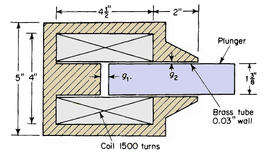 |
| Figure 4-11. Cylindrical plunger magnet for Problem 4-11 |
a brass guide tube of 0.03-in. wall thickness. The length of the air gap g1 varies with the position of the plunger, whereas the gap g2 is fixed by the wall thickness of the brass tube and is assumed constant of length 0.03 in. The relative permeability of brass is 1. Neglect magnetic leakage, fringing and the reluctance of the iron.
(a) Calculate for length of gl = 0.125 and 0.500 in.
(i) The magnetic reluctance,
(ii) The magnetic permeance of the two gaps in series.
(b) Calculate the flux in the magnet for each air-gap length in part (a) when the winding carries a constant current of 2.2 amp.
(c) Calculate the force on the plunger for each air-gap length in part (a) when the current is 2.2 amp, based on Eq. 4-67.
(d) Express the self-inductance of the magnet as a function of g1 when g1 is in inches and when it is in meters.
(e) Calculate the mechanical energy associated with the movement of the plunger when the air gap gl is decreased from a length of 0.500 in. to 0.125 in. while the current remains constant at a value of 2.2 amp. Is motor action or generator action involved? Explain.
(f) Calculate the electrical energy required to hold the current constant at 2.2 amp while g1 is decreased from a length of 0.500 in. to 0.125 in.
(g) Calculate the change in the energy stored in the field for parts (e) and (f)
above,
(h) If the value of the current is 2.2 amp when gl = 0.500 in. and the flux
remains constant, what is
(i) The value of the current when g1 = 0,125 in.?
(ii) The electrical energy associated with the motion of the plunger?
(iii) The change in the stored energy from g1 = 0.500 in. to g1 =0.125 in.?
|
| 4-12 |
Figure 4-12 shows a rotary electromagnet with a uniform air gap between the stator and the rotor. The self-inductance of the stator coils 1-1' and
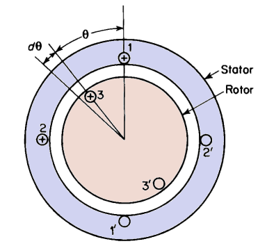 |
| Figure 4-12. Rotary electromagnet for Problem 4-12 |
2-2' is L11 = L22 = 0.20 h and the self-inductance of the rotor coil 3-3' is 0.10 h. The mutual inductances between the stator coils and the rotor coil are L13 =0.125[1 -(2θ/π)]h and L23 = 0.250θ/πh when the rotor is in the position shown.
(a) Calculate the torque when the currents are in the directions indicated and have the following values
i1 = +10 amp,
i2 = +5 amp,
i3 = +15 amp
for θ = 30°.
(b) What is the value of Θ at which the torque is zero for the values of current in part (a) ?
|
| 4-13 |
Figure 4-13 shows the magnetization curve of an iron-core reactor. The exciting winding has 400 turns and carries a direct current of 4 amp. The
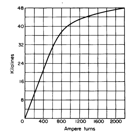 |
| Figure 4-13. Saturation curve of magnetic circuit with air gap for Problem 4-13.
|
leakage flux is negligible. Determine
(a) The magnetic flux.
(b) The magnetic flux linkage λ.
(c) The apparent inductance La.
(d) The effective inductance Le.
(e) The differential inductance Ld.
(f) The range of currents for which the three inductances La, Le, and Ld have the same value.
|
| 4-14 |
The hypothetical magnetization curve shown in Fig. 4-14 approximates that of an electromagnet. Express the energy WΦ stored in the magnetic field and the coenergy WΦ' in terms of i1, i2, λ1 and λ2 for a current of i1. amp and for a current of i2 amp.
|
| 4-15 |
Find the change in the energy stored in the field, the change in the coenergy, and the electromagnetic energy input when the air gap in the electromagnet having the hypothetical magnetization curves shown in Fig. 4-15 changes from g1 to g2
(a) While the mmf is held constant at 6.0 amp.
(b) While the flux linkage is held constant at 0.12 weber turn.
(c) If the locus of λ vs i during the change in gap is along the line ab.
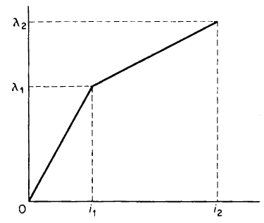 |
| Figure 4-14. Hypothetical magnetization curve for Problem 4-14 |
|
| 4-16 |
Calculate the average forces for parts (a), (b), and (c) in Problem 4-15 if the change in air-gap length from g1 to g2 is 0.10 in. Does the length of the air gap increase or decrease in going from g1 to g2? Explain.
|
| 4-17 |
The no-load current in a transformer winding is 9.1 amp when the voltage across the same winding is 6,600 v at 60 cycles. The real power is 9,300 w. Determine
(a) The reactive power.
(b) The Q of this transformer winding at no load on the basis of the real and reactive power.
|
| 4-18 |
A choke coil has a self-inductance of 9,0 h. The effective resistance of the winding is 250 ohms at a frequency of 1000 cps. Determine the Q of the
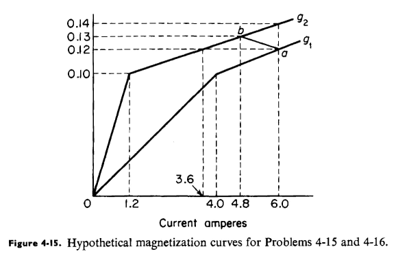 |
| Figure 4-15. Hypothetical magnetization curves for Problems 4-15 and 4-16 |
choke for a frequency of
(a) 1000 cps.
(b) 60 cps on the basis that the self-inductance and the effective resistance have the same values as at 1000 cps.
|
| 4-19 |
Prove that Eqs. 4-109, 4-110, and 4-111 are equivalent.
|

 Inductance - Electromagnetic Energy Conversion


