| Capacitors, Magnetic Circuits, and Transformers is a free introductory textbook on the physics of capacitors, coils, and transformers. See the editorial for more information.... |
|
Home  Excitation Characteristics of Iron-Core Reactors Voltage Current and Flux Relations Excitation Characteristics of Iron-Core Reactors Voltage Current and Flux Relations |
|||||||||||||||||||||||||||||||||||||||||||||||


|
  |
||||||||||||||||||||||||||||||||||||||||||||||
Voltage Current and Flux Relations
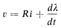
Figure 5-1 is a schematic diagram of an air-core reactor. Assume the frequency of the voltage and the size of the winding to be low enough so that capacitance effects are negligible. Then if v is the instantaneous applied voltage, i the instantaneous current, R the resistance of the winding, and λ the instantaneous flux linkage, we have
or
where e is the induced emf and equals the instantaneous change in the flux linkage λ. In Fig. 5-1, when the current is increasing while flowing in the indicated direction, the flux linkage λ is increasing and the voltage e is positive with polarities as shown. Hence
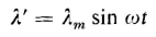
If the flux linkage varies sinusoidally with time as expressed by
where λm is the maximum instantaneous flux linkage, N is the number of turns in the winding of the reactor and Φ is the equivalent flux linking all
N turns, then
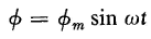
from which it follows that
where Φm is the maximum value of the equivalent flux. Substitution of Eqs. 5-6 and 5-7 in 5-2 gives
and the instantaneous emf is
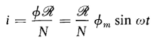
Since the magnetization curve of air is linear, the current in the case of an air-core has exactly the same wave form as the flux when expressed as a function of time. In addition, the current wave is in time phase with the flux wave. This follows from Ohm's Law of the magnetic circuit, i.e.
Where R is the reluctance of the magnetic path and also constant for air. Hence, from Eqs. 5-7 and 5-10
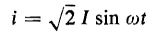
which, when expressed in terms of the effective value of the current I, becomes
where In the case of a reactor that has a ferromagnetic core of uniform cross section and where the length of flux path is great enough in relation to the cross-sectional area of the path so that the flux density may be considered uniform, the relationship between the flux Φ and the current in the winding is not linear, but is represented graphically by a hysteresis loop. Under these conditions we have
where B is the flux density and A the cross-sectional area of the flux path. Also
and
In the hysteresis loop, the flux density B is normally plotted against the magnetic field intensity H. Hence, when plotting Φ against i, the effect is merely that of multiplying the horizontal scale of the loop by l/N. Both these multipliers-A and l/N-are constant and the shape of the loop is unchanged. Figure 5-3 shows the upper half of such a hysteresis loop. The bottom of the loop has the same shape as the upper half. This loop shows the relationship between the instantaneous flux Φ and the instantaneous current i in the winding on the basis that the eddy currents are negligible. The effect of the eddy currents is to widen the loop somewhat. This is evident from the fact that the eddy currents are in phase with the voltage and are therefore at maximum value when the flux is zero because the current wave is 90° behind the voltage wave. A loop that includes the effect of eddy currents is known as a dynamic hysteresis loop. Suppose that the resistance of the reactor winding is negligible. (This is true for many iron-core reactors.) Furthermore, let a sinusoidal voltage
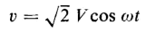
be applied to the reactor winding. The flux in the core will also be a sine wave as expressed by Eq. 5-4. However, the flux wave lags the voltage by 90°. Generally, in iron-core reactors the leakage flux is small enough so that the flux in the core may be related to the voltage as in Eq. 5-9, and we have
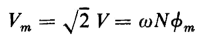
which is a sinusoid with an amplitude of
where f is the frequency in cycles per second, so that
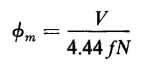
from which the flux is found to be
The factor 4.44 in Eq, 5-19 applies only to a sinusoidal voltage wave, A more general expression is
where the form factor is the ratio of the rms value to the average value of one-half the wave. In case of a square voltage wave, the rms and average values are equal, and the form factor is unity. The form factor of a sine wave is 1.11.
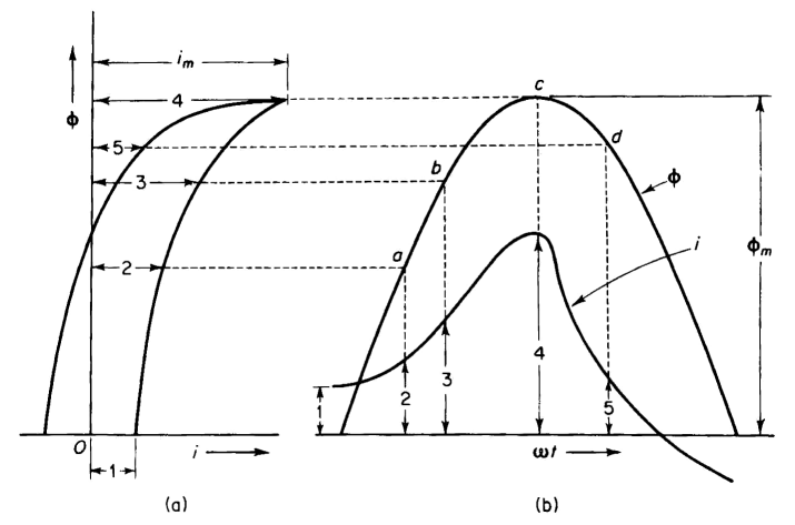
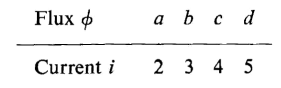
The flux is plotted as a function of time in Fig. 5-3(b). If the hysteresis loop could be represented by a straight line, the current would have the same wave form as the flux. However, this not being the case, the current cannot have the same wave form as the flux. The wave form of the current, if eddy current is neglected, is found graphically as follows. When the flux is zero and increasing, the instantaneous current is 1 on the hysteresis loop and is shown as 1 in Fig. 5-3(b). When the flux is a and increasing, the current is 2 on the hysteresis loop. This can be continued in the following tabulation.
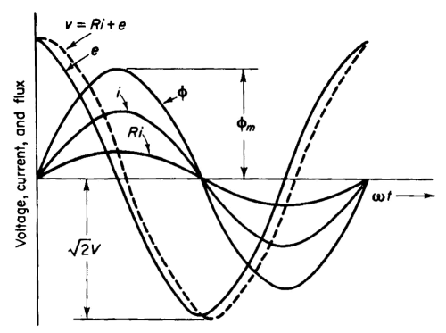
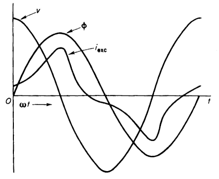
Thus, by plotting the values 1, 2, 3, 4, 5 for the current along the time axis in Fig. 5-3(b) on the flux values 0, a, b, c, d, the wave form of the current is obtained. In order to obtain a well-defined current wave, a greater number of points than those listed in the tabulation above are required. From Fig. 5-3 it is evident that, although the flux varies sinusoidally with time, the current is not a simple sinusoidal function of time, but is distorted. In addition to the current shown in Fig. 5-3(b), there is a small component due to the eddy currents. This component of current is practically sinusoidal and is in phase with the voltage or 90° ahead of the flux wave. Waves of voltage, flux, and current are shown for an iron-core reactor with a winding of negligible resistance in Fig. 5-4. The voltage wave is sinusoidal - so is the flux wave - but the current wave is not. The flux wave lags the voltage wave by 90° since the winding was assumed to have negligible resistance.
|
|||||||||||||||||||||||||||||||||||||||||||||||
| Home Excitation Characteristics of Iron-Core Reactors Voltage Current and Flux Relations |
|
||||||||||||||||||||||||||||||||||||||||||||||


 I is the amplitude of the current wave. Wave forms of current and voltage for an air-core reactor are shown in Fig. 5-2.


Last Update: 2011-02-16