| Capacitors, Magnetic Circuits, and Transformers is a free introductory textbook on the physics of capacitors, coils, and transformers. See the editorial for more information.... |

|
Home  Excitation Characteristics of Iron-Core Reactors Equivalent Circuits Excitation Characteristics of Iron-Core Reactors Equivalent Circuits |
|||||||||||||


|
  |
||||||||||||
Equivalent Circuits
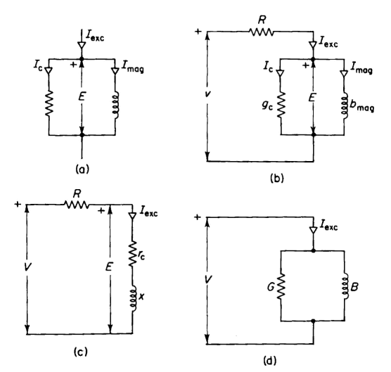
On the basis of Section 5-6, equivalent circuits are used to represent iron-core reactors in circuit analysis. A reactor may be represented by one of several different equivalent circuits, all of which are approximate. The phasor diagram of Fig. 5-9 suggests a parallel circuit as shown in Fig. 5-10(a). This equivalent circuit does not take into account the resistance of the reactor winding. However, the induced voltage E is produced by the flux linkage with the reactor winding. The instantaneous voltage applied to the winding of a reactor is given by Eq. 5-2 and 5-3 as
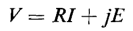
where e is the instantaneous induced voltage. In the case of sinusoidal voltage and current, the relationship in Eq. 5-3 can be expressed in phasor form as
where V = applied voltage (rms)
Although Eq. 5-3 is exact, the equivalent circuit and Eq. 5-51 are approximations since the current is not sinusoidal. Nevertheless, these approximations are very useful in many analyses, and the errors resulting therefrom are usually negligible. The equivalent circuits of Figs. 5-10(b) and 5-10(c) satisfy Eq. 5-51. In Fig. 5-10(d) the circuit parameters G and B include the effect of the winding resistance. In Fig. 5-10(c)
where P is the real power in watts. In the same figure
It is customary in the equivalent series circuit to lump R + rc into a resistance Ra, the apparent resistance. In Fig. 5-10(d)
and
The parameters rc, x, G, and B are not constant and a given value for any of them is valid only for the particular frequency and degree of magnetic saturation for which it was obtained. The terms rc and G arise from core loss, which is a function of frequency and flux density. Similarly, x and G are functions of frequency and of magnetic permeability. For example, if the voltage is increased while the frequency is held constant, the magnetic flux density increases, causing the magnetic saturation to increase, thereby producing an increase in the value of the susceptance B and a corresponding decrease in the reactance x. If the core losses varied as the square of the voltage, the conductance G would remain constant and the resistance rc would decrease. However, the core losses vary at a rate that is somewhat less than the square of the voltage. Consequently, the conductance G decreases with increasing voltage.
|
|||||||||||||
| Home Excitation Characteristics of Iron-Core Reactors Equivalent Circuits |
|
||||||||||||


Last Update: 2011-02-16