| Capacitors, Magnetic Circuits, and Transformers is a free introductory textbook on the physics of capacitors, coils, and transformers. See the editorial for more information.... |

|
Home  Excitation Characteristics of Iron-Core Reactors Core-Loss Current and Magnetizing Current Excitation Characteristics of Iron-Core Reactors Core-Loss Current and Magnetizing Current |
|||||||||||||||||


|
  |
||||||||||||||||
Core-Loss Current and Magnetizing Current
The fundamental, 3rd, and 5th harmonic components of the current in a reactor are shown in Fig. 5-6. Such a current could also be the exciting current or no-load current in a transformer. The fundamental component iexc1 is shown in Fig. 5-7 along with the flux wave Φ and induced voltage wave e. Sinusoidal flux variation is assumed. In Section 5-4 it was shown that in the case of sinusoidal voltage the harmonics in the current wave do not contribute to the real power. Therefore, core loss, i.e., hysteresis and eddy-current losses, can be taken into account by taking the product of the induced emf and the component of the fundamental in the current that is in phase with the induced emf. This component of current is called the core-loss current and is represented by ic in Fig. 5-7.
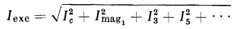
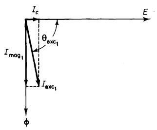
If the current wave representing the core-loss current ic is subtracted from the total fundamental component of current iexc1, the result is a sine wave of current that is in phase with the flux wave Φ. If there were no harmonics, this latter component of current would be the magnetizing current. Under these conditions the two currents, i.e., core-loss and magnetizing currents, as well as the flux and the induced voltage, could be represented by the phasor diagram shown in Fig. 5-8. However, the magnitude of the exciting current is actually greater than that resulting from the fundamental component, as it does include all the harmonic components. Since the harmonics in the exciting current do not contribute to the real power if the induced voltage is sinusoidal, the core-loss component Ic in Fig. 5-8 is not affected by inclusion or exclusion of the harmonics. In accordance with Eq. 5-46, the exciting current has an rms or effective value of
It must be kept in mind that under a-c excitation, in the absence of a d-c component, only odd harmonics are present in the exciting current.
The following relationship is obtained from Eq. 5-48
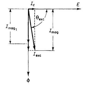
Generally, phasor diagrams apply to sinusoidal quantities, but may be used to include nonsinusoidal currents and voltages if these are replaced by equivalent sinusoidal quantities, i.e., sinusoids that have the same rms or effective values. If the exciting current is represented by a phasor Iexc as in Fig. 5-9 and is treated as an equivalent sinusoidal current, the phasor difference expressed by the right-hand side of Eq. 5-49 leads to a phasor that lags the core-loss current by 90°. The equivalent sinusoid represented by this phasor is called the magnetizing current, and from Eq. 5-49 is seen to be
Equation 5-50 suggests that the harmonic components be included in the magnetizing component of the exciting current. This facilitates the development of a phasor diagram and a simple equivalent circuit. A phasor diagram including the harmonics in the magnetizing current is shown in Fig. 5-9.
|
|||||||||||||||||
| Home Excitation Characteristics of Iron-Core Reactors Core-Loss Current and Magnetizing Current |
|
||||||||||||||||


Last Update: 2011-02-16