| Capacitors, Magnetic Circuits, and Transformers is a free introductory textbook on the physics of capacitors, coils, and transformers. See the editorial for more information.... |

|
Home  The Transformer Equivalent Circuit of the Transformer The Approximate Equivalent Circuit The Transformer Equivalent Circuit of the Transformer The Approximate Equivalent Circuit |
|||||


|
  |
||||
The Approximate Equivalent Circuit
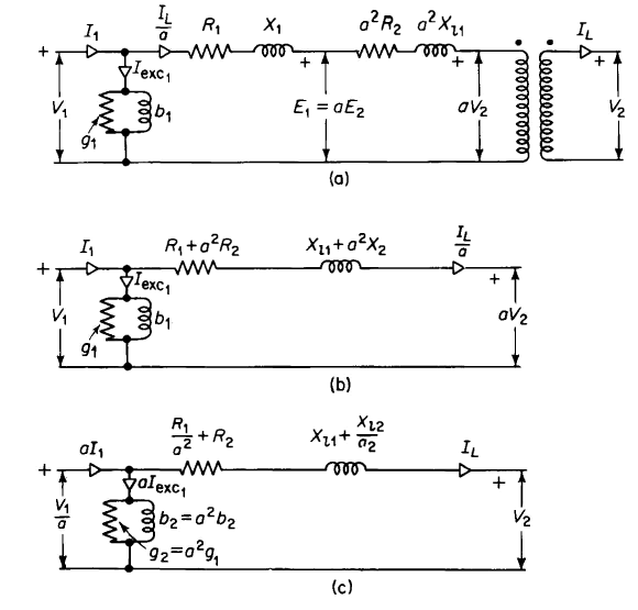
Calculations involving transformers seldom require the accuracy of the exact equivalent circuit and can be simplified by using the approximate equivalent circuits shown in Fig. 6-14. The equivalent circuits in Fig. 6-14 neglect the effect of the exciting current in the voltage drop across the primary leakage impedance. However, the error in the value computed for the primary applied voltage V1 is quite small, as is evident from the fact that in Example 6-2 the primary applied voltage V1 is 2457 v, as compared with a value of 2428 v for the primary induced emf E1 Here we have a difference of 29 v in the magnitude of the two voltages V1 and El due to rated current. The exciting current, which has a magnitude of only about 1.7/62.5, or less than 3 percent of rated current, would account for a difference of only about 1 v or only 1 part in about 2400. The exciting current that results from impressing the primary terminal voltage on the exciting admittance is only a few percent greater than that produced by the primary induced voltage E1. Since the exciting current is only a few percent of rated current in iron-core transformers, a change of a few percent in the exciting current
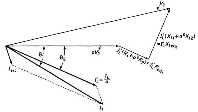
itself is a very small change when compared with the value of the rated current. In view of the rather small effect on the voltage drops in the transformer windings and on the exciting current produced by moving the exciting admittance to the part of the circuit that corresponds to the primary terminals of the transformer, the approximate equivalent circuit is valid for most transformer calculations. The phasor diagram for the approximate equivalent circuit is shown in Fig. 6-15.
|
|||||
| Home The Transformer Equivalent Circuit of the Transformer The Approximate Equivalent Circuit |
|
||||
Last Update: 2011-01-06