| Capacitors, Magnetic Circuits, and Transformers is a free introductory textbook on the physics of capacitors, coils, and transformers. See the editorial for more information.... |

|
Home  The Transformer Open-Circuit and Short-Circuit Tests The Transformer Open-Circuit and Short-Circuit Tests |
|||||||||||||||||||||||||||||||||||||||||


|
  |
||||||||||||||||||||||||||||||||||||||||
Open-Circuit and Short-Circuit Tests, Exciting Admittance, and Equivalent Impedance
The constants of the transformer for the approximate equivalent circuit can be determined from the open-circuit and short-circuit tests. The open-circuit test is made to obtain the values of the exciting-admittance, conductance, and susceptance. In the case of power transformers or constant-voltage transformers operating at one specified frequency, the open-circuit test consists in the application of rated voltage at rated frequency usually to the low-voltage winding with the high-voltage winding open circuited. Measurements are made by means of indicating instruments (voltmeter, ammeter, and wattmeter) of voltage, current, and power. Actually, the open-circuit test can be made by applying rated voltage at rated frequency to the high-voltage winding with the low-voltage winding open circuited. However, it is usually more convenient to work on the low-voltage side because the lower voltage is easier to handle.
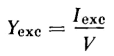
The quantities involved in most communication transformers are generally too small for wattmeter and ammeter measurements. Methods involving the use of a-c bridges or other suitable devices are employed. In Fig. 6-16 let Iexc = the exciting current as read by the ammeter, A(1) Then the exciting admittance is
and the exciting conductance is
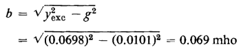
from which the exciting susceptance is found to be
The short-circuit test yields results from which the equivalent impedance, equivalent resistance, and equivalent leakage reactance of the transformer can be evaluated. In Fig. 6-14(b) the equivalent impedance of the transformer referred to the primary is
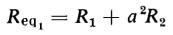
in which the equivalent resistance referred to the primary of the transformer is
and the equivalent leakage reactance referred to the primary is
The equivalent impedance referred to the secondary is
from which
and
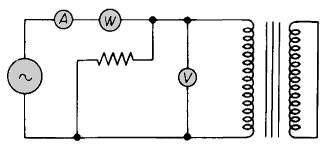
It is the general practice, in the short-circuit test, to short circuit the low-voltage winding and to apply voltage, at rated frequency, such that rated current flows in the transformer. Measurements are made of input current, power, and voltage, using indicating instruments, i.e., ammeter, wattmeter, and voltmeter as shown in Fig. 6-17. Again, in the case of communication transformers, an a-c bridge method or an arrangement adapted for measuring the smaller quantities associated with such transformers is used.
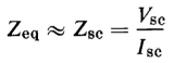
The short-circuit test could also be made by short circuiting the high-voltage side and making the measurements on the low-voltage side. This, however, is more inconvenient since the applied voltage is low and the measured current high. These quantities are handled and measured more readily on the high-voltage side. For the short-circuit test let Vsc = applied voltage as read by the voltmeter, V (in Fig. 6-17) The voltage Vsc is low in comparison with the rated voltage. It can be shown that, in the case of the transformer of Example 6-2, the short-circuit voltage is less than 3 percent of rated value, On that basis, the exciting current can be neglected and the short-circuit impedance Zsc assumed to equal the equivalent series impedance of the transformer. Hence, the equivalent series impedance is
and the equivalent series resistance is practically equal to the short-circuit resistance
Also, the equivalent leakage reactance of the transformer is
|
|||||||||||||||||||||||||||||||||||||||||
| Home The Transformer Open-Circuit and Short-Circuit Tests |
|
||||||||||||||||||||||||||||||||||||||||


Last Update: 2011-01-15