| Capacitors, Magnetic Circuits, and Transformers is a free introductory textbook on the physics of capacitors, coils, and transformers. See the editorial for more information.... |

|
Home  The Transformer Multicircuit Transformers The Transformer Multicircuit Transformers |
|||||||||||||||||||||||||||||||||||||||||||||||||||||||||


|
  |
||||||||||||||||||||||||||||||||||||||||||||||||||||||||
Multicircuit Transformers
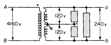
Three or more circuits that may have different voltages are frequently interconnected by means of one transformer, known as a multicircuit or multiwinding transformer. Such an arrangement is more economical than one in which two or more 2-circuit or 2-winding transformers effect the same interconnection. For example, distribution transformers have a primary winding usually rated at 2000 v or above, and generally have two 120-v secondaries connected in series with their common or neutral grounded as shown in Fig. 6-35.
The secondaries thus supply a 240/120/120-v 3-wire circuit, in which the load comprised of the ordinary 120-v appliances is connected from line to neutral so that this load is divided about equally between the two 120-v windings. Appliances that operate at 240 v, such as electric stoves, are connected across the two windings in series. 3-winding transformers are also commonly used to supply electron tube circuits where one winding supplies the plate current at one voltage and another winding supplies current to the cathode heaters at a lower voltage than that applied to the plate circuit. Large power transformers used in 3-phase installations are frequently provided with three windings, the primary and secondary of which are connected for wye-wye operation, whereas the tertiary windings are connected in delta to maintain balanced voltage and to provide a path for the third harmonics in the exciting current.
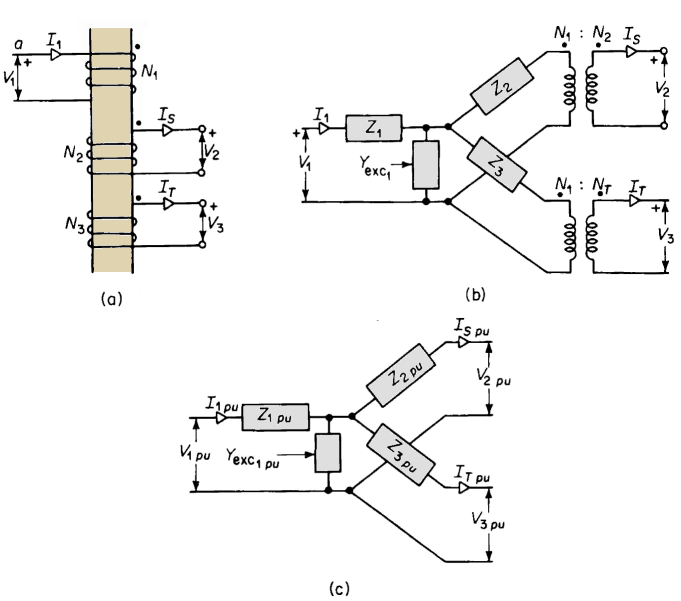
The windings of a 3-circuit transformer are represented schematically in Fig. 6-36(a). If the transformer were ideal, i.e., had no leakage impedance and no exciting admittance, the following relationship would obtain
where V1, V2, and V3 are the primary, the secondary, and the tertiary terminal voltage respectively, and N1, N2, and N3 are the turns in the respective windings. Further, i1, iS, and iT are the instantaneous currents in the primary, the secondary, and the tertiary windings respectively. From Eq. 6-106 it follows that the effective ampere turns in the primary winding must be the phasor sum of the effective ampere turns in the secondary and tertiary windings. Hence
However, when the leakage impedance and the exciting admittance are taken into account the equivalent circuit of a three-circuit or three-winding transformer is as shown in Figs. 6-36(b) and 6-36(c). Open-circuit and short-circuit tests The open-circuit test, made in the same manner as the test for a 2-winding transformer, yields the data from which the exciting admittance can be determined. However, since there are three circuits, it is necessary to make three short-circuit tests to obtain the data for the equivalent circuits of Figs. 6-36(b) and 6-36(c). Assume the tertiary to have the lowest voltage rating, the primary to have the highest voltage of the three windings, and the secondary to have a voltage rating between those of the tertiary and the primary. The short-circuit tests are then usually made as follows 1. Voltage applied to the primary with the secondary winding short circuited and the tertiary open circuited. The exciting current is negligible and the measured impedance will be
2. Voltage applied to the primary with the tertiary short circuited and with the secondary open, from which
3. Voltage applied to the secondary with the tertiary short circuited and with the primary open, whence
and
where VS is the voltage applied to the secondary and ISsc is the secondary current with the tertiary short circuited and the primary open. The leakage impedances Z1, Z2, and Z3, all of which are referred to the primary, are found as follows
Multicircuit transformers are not limited to three circuits but may have a greater number. When the number of circuits or windings exceeds three, the analysis and the equivalent circuits are considerably more complicated than for the 3-winding transformers and are, therefore, not included in this book.
|
|||||||||||||||||||||||||||||||||||||||||||||||||||||||||
| Home The Transformer Multicircuit Transformers |
|
||||||||||||||||||||||||||||||||||||||||||||||||||||||||


 will suffice as a base for all three impedances.


Last Update: 2011-02-16