| 6-1 |
Figure 6-37 is a schematic diagram of an ideal transformer supplying a noninductive resistance R = 10 ohms. The primary winding has N1 = 100
turns and the secondary winding has N2 = 50 turns. The instantaneous voltage applied to the primary winding is v1 = 150 v.
(a) What is the value of the current and its direction through the resistance R?
(b) What is the value of the primary current?
(c) What is the direction of the flux in the core?
(d) What is the rate of change of
(i) The flux in the primary winding ?
(ii) The flux linkage with the primary winding?
(iii) The flux in the secondary winding?
(iv) The flux linkage with the secondary winding?
(e) The transformer and its connected load are replaced by a noninductive resistance which takes the same value of current at 150 v as that in the primary of the transformer. What is the value of the resistance in ohms?
(f) What is the ratio of the resistance in part (e) to that of the resistance R in the secondary? What is this ratio called?
(g) A polarity mark is shown near the upper terminal of the primary winding in Fig. 6-37. Where should the secondary polarity mark be placed?
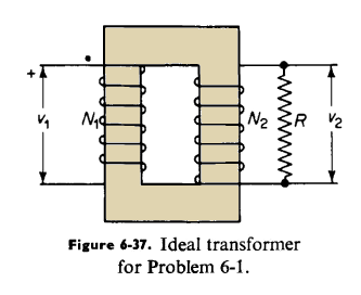 |
| Figure 6-37. Ideal transformer for Problem 6-1 |
|
| 6-2 |
The purpose of this problem is to show, firstly, that a sizeable reduction in frequency without a corresponding reduction in voltage leads to values of exciting current that can exceed the rated current of the transformer, and secondly, that a reduction of the voltage to a value that leads to a safe value of exciting current lowers the rating of the transformer.
A 1,500-w, 240/25-v, 400-cycle transformer operates at a maximum flux density of 36,000 lines per sq in. and the peak value of the exciting current is 0.20 amp.
(a) Use the magnetization curve of Fig. 3-11 and determine the peak value of the exciting current when the primary of this transformer is connected to 120-v 60-cycle source. Neglect resistance and leakage flux.
(b) Suppose this transformer were to operate at a frequency of 60 cps and at magnetic flux density Bm = 90,000 lines per sq in., and the current density in the windings is the same as for rated 400-cps operation. What would the rating of the transformer be in volt-amperes?
|
| 6-3 |
An audio output transformer operates from a 4,000-ohm resistance source delivering 5 w to a noninductive load of 10 ohms. Assume the transformer to be ideal and determine
(a) The turns ratio such that the load impedance referred to the primary has a value of 4,000 ohms.
(b) The secondary and primary currents.
(c) The primary applied voltage.
|
| 6-4 |
An ideal transformer is represented schematically in Fig. 6-38. Note the current directions and voltage polarities and draw a phasor diagram on a one-to-one ratio basis for these directions and polarities. Assume the load current to lag the load voltage by an angle of 30°.
 |
| Figure 6-38. Ideal transformer for Problem 6-4 |
|
| 6-5 |
The secondary winding of the transformer in Example 6-2 is short circuited and sufficient voltage, at rated frequency, is applied to the primary winding so that rated current flows in the secondary. On the basis of the exact equivalent circuit in Fig. 6-11 (a) determine
(a) The secondary induced emf E2.
(b) The primary induced emf E1.
(c) The core-loss current on the basis that the exciting admittance is constant. (Actually, the exciting admittance is not constant; for one thing, it increases with increasing magnetization of the core.)
(d) The exciting current based on the admittance of part (c) above.
(e) The primary applied voltage V1.
(f) The per unit impedance of the transformer on the basis that the per unit impedance is defined as the ratio of the voltage V1 with rated current on short circuit in part (e) above, to the rated primary voltage.
(g) The per unit resistance of the transformer on the basis that the ratio of
the I2R losses with rated current to the volt-ampere rating of transformer is the per unit resistance,
(h) The mutual flux expresssed as a decimal fraction of the mutual flux at rated voltage and no load,
(i) The primary current and the secondary current when a short circuit is
applied to the secondary with full rated voltage across the primary.
|
| 6-6 |
Repeat Problem 6-5, using the equivalent circuit of Fig. 6-14(a).
|
| 6-7 |
(a) Determine the current, real power, and reactive power when a 60-cycle emf of 240 v is applied to the secondary winding of the transformer in Example 6-2 when the primary winding is open.
(b) Determine the current, real power, and reactive power when a 60-cycle emf of 2,400 v is applied to the primary of the transformer above with the secondary open.
|
| 6-8 |
The results of an open-circuit test and short-circuit test at rated frequency on a 500-kva 42,000/2,400-v, 60-cycle transformer are as follows
Open-circuit Test - Voltage applied to Low-voltage Side
2400 Volts
18.1 Amperes
3785 Watts
Short-circuit Test - Low-voltage Side Short Circuited
1910 Volts
11.9 Amperes
3850 Watts
(a) Determine the following quantities referred to the high-voltage side of the transformer.
(i) The exciting admittance, conductance, and susceptance.
(ii) The equivalent leakage impedance,
(iii) The equivalent resistance.
(b) Repeat part (a), referring all quantities to the low-voltage side.
(c) Determine the leakage reactance of each winding on the basis that the same amount of equivalent leakage flux links each winding.
(d) Determine the resistance of each winding on the basis of equal amounts of copper and equal current densities in the two windings.
(e) Repeat part (d), but on the basis that the length of the mean turn in the high-voltage winding is 40 percent greater than that in the low-voltage winding.
|
| 6-9 |
Determine the efficiency of the transformer in Problem 6-8 when delivering at 2,400 secondary v.
(a) Rated load at unity power factor.
(b) At 1/4, 1/2, 3/4, 1 and 5/4 rated load all at 0.80 power factor.
|
| 6-10 |
Determine the regulation of the transformer in Problem 6-8 when delivering rated load at 0.80 power factor
(a) Current lagging.
(b) Current leading.
|
| 6-11 |
The transformer in Problem 6-8 is a core type and has its high-voltage winding surrounding the low-voltage winding, which is next to the core. If the low-voltage winding were left unchanged, and the high-voltage winding were
rewound for 69,000 v without a change in the amount of copper and without appreciable change in the space, as to both amount and configuration, what would be the
(a) Equivalent resistance of the transformer referred to
(i) The low-voltage side?
(ii) The high-voltage side?
(b) Equivalent leakage reactance of the transformer referred to
(i) The low-voltage side?
(ii) The high-voltage side?
(c) The exciting current at normal excitation (69,000/2,400-v operation) on
(i) The low-voltage side?
(ii) The high-voltage side?
|
| 6-12 |
A 240/120-v autotransformer delivers a current of 180 amp to a load connected to the low side. Neglect the exciting current and determine the current in each of the windings.
|
| 6-13 |
A 2,400/240-v transformer has an efficiency of 0.94 at rated load 0.80 power factor when operating as a 2-circuit or 2-winding transformer. This transformer is reconnected to operate as an autotransformer with the windings carrying their rated currents and feeding a 0.80 power factor load. Show a diagram of connections and determine the efficiency when the autotransformer is connected for operation
(a) 2,640/2,400 v.
(b) 2,400/2,640 v.
(c) 2,400/2,160 v.
(d) 2,640/240 v.
|
| 6-14 |
The data for an output transformer are as follows
Resistance of primary winding R1 = 225 ohms
Resistance of secondary winding R2 = 0.52 ohms
Primary short-circuit inductance Lsc1 = 0.10 h
Primary open-circuit inductance Loc1 = 5.85 h
Turns ratio a = 20.
This transformer is connected between a source and the voice coil of a loud speaker. The source has an internal impedance of 2,000 ohms and the voice coil has an impedance of 8 ohms. Both of these impedances are practically noninductive. The power output of the transformer is 6 w. Assume the frequency to be of such a value that the exciting current and the leakage reactance of the transformer are negligible, and determine
(a) The secondary current in the transformer.
(b) The a-c component in the primary of the transformer.
(c) The internal a-c emf of the source.
|
| 6-15 |
Suppose that this transformer in Problem 6-14 were redesigned without any changes in the core and secondary winding, but that the turns in the primary windings were changed, keeping the amount of copper the same as before, so that the impedance of the voice coil exactly matches that of the source and the transformer. If the voltage and frequency were the same as in Problem 6-14
(a) What would be the new power supplied to the loud speaker voice coil?
(b) What percentage increase is this over the corresponding amount in Problem 6-14?
|
| 6-16 |
Determine for the transformer in Problem 6-14
(a) The upper and lower half-power frequencies fh and fl.
(b) The geometric mean frequency f0.
(c) The ratio fh/fl.
|
| 6-17 |
Repeat Problem 6-16 for a transformer having an identical core, the same amount of copper in the windings, but in which the number of turns in the primary and secondary is 20 percent greater than in the corresponding windings of the transformer in Problem 6-16.
|
| 6-18 |
Three single-phase transformers are to be connected for 4,000/440-v, 3-phase operation. The voltages are line to line. The 3-phase rating is to be 750 kva. There are four ways of connecting this transformer bank. Show a diagram of connections for each of the four ways and specify the voltage and current ratings of both windings in each transformer for each of the connections.
|
| 6-19 |
Figure 6-39 shows a bank of three single-phase, one-to-one ratio transformers with one side connected in wye to a 416-v, 3-phase source with the neutral grounded. The other side of the bank is connected in delta with the center tap of one phase grounded. The source is completely ungrounded.
 |
| Figure 6-39. Wye-delta transformer bank for Problem 6-19 |
Determine
(a) The line-to-ground voltages on the high and low sides of the transformer bank.
(b) The voltages A-a, A-b, and A-c.
(c) The voltages A-a, A-b, and A-c if the polarity of both windings in the middle transformer of Fig. 6-39 is reversed.
(d) Repeat parts (a) and (b) if C-phase terminal of the 416-v side is grounded instead of the neutral,
|
| 6-20 |
A 12,000-v, 3-phase bus supplies (1) a bank of three single-phase transformers connected delta-delta and delivering a balanced 3-phase load of 5,000 kva, 0.90 power factor, current lagging, at 4,000 v and (2) a delta-wye connected, 3-phase transformer delivering a balanced 3-phase load of 2,500 kva, 0.71 power factor, current lagging, at 2,300 v. Determine the total load supplied to the two transformer arrangements by the 12,000-v bus. Neglect the exciting current and leakage impedance of the transformers.
|
| 6-21 |
Two identical 4,000/240-v, single-phase transformers are connected open delta and have a 3-phase rating of 11.53 kva. What is the 3-phase rating if another similar transformer is added for delta-delta operation?
|
| 6-22 |
Suppose that windings A and C in the 3-phase, core-type transformer in Fig. 6-29(a) were connected in parallel to a 100-v a-c source and windings B, a, b, and c were open circuited. How much voltage would be induced in the B winding if
(a) The A and C windings have their marked (polarity) terminals connected together and their unmarked terminals connected together?
(b) The marked terminal of A is connected to the unmarked terminal of C and the unmarked terminal of A is connected to the marked terminal of C? Assume the transformer to be ideal.
|
| 6-23 |
Describe the effect of exciting windings A, B, and C in parallel with
(a) Like polarities of all three windings connected together, at rated voltage and frequency from a single-phase source.
(b) The polarity of B winding reversed.
|
| 6-24 |
Repeat Problem 6-22 for the 3-phase shell-type transformer in Fig. 6-29(b), assuming the reluctance of the vertical components in the flux paths to equal that of the horizontal components. For example, in following around the flux path through the windings B and b in the center of the core, each vertical section marked y and each outer horizontal section has twice the reluctance of the horizontal center portion between points marked x.
|
| 6-25 |
Repeat Problem 6-23 for the 3-phase shell-type transformer in Fig. 6-29(b).
|
| 6-26 |
Is it possible to operate one or both of the transformers in Fig. 6-29 at rated voltage and frequency as a single-phase transformer without excessive exciting current by connecting all three primary windings in parallel with each other and all three secondary windings in parallel with each other?
|
| 6-27 |
Three single-phase transformers, each rated 2,400/240/120 v and lOkva, have their primaries connected in delta and the center taps on their secondaries to form a neutral for 6-phase operation, as shown in Fig. 6-30. Determine the line-line voltages on the 6-phase side and the rated current in the 6-phase line wire.
|
| 6-28 |
A 6-phase forked-wye connection, with the primary connected 3-phase delta, converts 13,800v 3-phase to 500 v line to line on the 6-phase side. The secondaries of each phase are divided into three equal sections. Determine the ratio of primary turns to all the turns in the secondary winding.
|
| 6-29 |
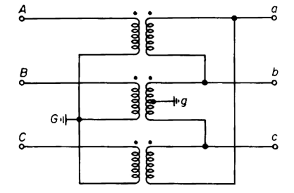
Three identical single-phase, 10,000-kva transformers are connected delta on the 22-kv side and wye on the 132-kv side with the neutral on the 132-kv side isolated. Balanced 3-phase voltages are applied to the 22-kv side such that
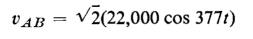
and the exciting current in the delta between A and B lines is
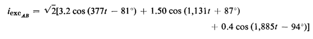
Express as functions of time
(a) The voltages vBC and vCA on the 22-kv side.
(b) The exciting currents iexcBC and iexcCA m the delta.
(c) The no-load current iexcA, iexcB, iexcC the 22-kv lines.
|
| 6-30 |
The three single-phase transformers of Problem 6-29 are operating without load and are excited from the 132-kv side with the neutral connected to the source. Assume a-phase, line-to-neutral voltage on the 132-kv side to be in phase with the line-to-line voltage between A and B phases on the 22-kv side. If the delta connection is opened
(a) How do the exciting currents iexca iexcb and iexcc vary as functions of time?
(b) How does the neutral current in vary as a function of time ?
|
| 6-31 |
The three single-phase transformers of Problems 6-29 and 6-30 are operating without load and are excited from the 132-kv side with the neutral isolated and the delta closed. Express the exciting currents iexca iexcb and iexcc as functions of time.
|
| 6-32 |
The distribution transformer in Fig. 6-35 delivers 30 amp at 120 v, 1.00 power factor a to n; 40 amp at 120 v, 0.707 power factor, current lagging b to n; 25 amp at 240 v, 0.90 power factor, current lagging a to b. Neglect transformer impedance and admittance and calculate the primary current and the primary power factor.
|
| 6-33 |
The transformer bank in Example 6-8 delivers a load of 60,000 kva, 0.80 power factor, current lagging to a balanced 3-phase load on the 11-kv side. There is no load on the 2.2-kv side. Neglect resistance and determine the voltage on
(a) The 66-kv side.
(b) The 2.2-kv side.
if the load voltage is 11-kv line to line.
|
| 6-34 |
Determine for the transformer of Example 6-2 the following base quantities
(a) On the high side.
(b) On the low side using the rating of the transformer for the base power,
(i) Current,
(ii) Voltage,
(iii) Impedance
|
| 6-35 |
Determine the per unit values of
(a) Exciting current
(b) Resistance
(c) Impedance
(d) Leakage reactance
of the transformer in Example 6-2, using the rating of the transformer as the base power.
|
| 6-36 |
Repeat Problem 6-35, but for a base kva of 450.
|
| 6-37 |
Determine the per unit resistance, reactance, and exciting current of the transformer in Problems 6-8 and 6-11, using the transformer rating as the base.
|
| 6-38 |
A 3-phase transformer rated at 150,000 kva, 138/13.8 kv has an impedance of 0.10 per unit and is operating at 132/13.2 kv. Calculate the per unit impedance for a 1,000,000-kva base and 132-kv base.
|

 The Transformer


