| Capacitors, Magnetic Circuits, and Transformers is a free introductory textbook on the physics of capacitors, coils, and transformers. See the editorial for more information.... |

|
Home  Saturable Reactors Operation With Free Even-Harmonics Saturable Reactors Operation With Free Even-Harmonics |
|||
| See also: Third Harmonics in 3-Phase Transformer Operation | |||


|
  |
||
Operation With Free Even-Harmonics
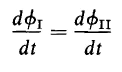
The operating principle for the series connection is practically the same as that for the parallel connection of gate windings, as long as the impedance of the control circuit is low enough to permit the circulation of even-harmonics produced in the control circuit by the current in the output windings or gate windings. The sum of the voltages taken around the control circuit must be zero in accordance with Kirchhoff 's Law. The impedance of the control circuit must be low enough to permit the circulation of free even-harmonics, and can therefore be neglected. Then, since the voltages across the two control windings must be equal at all times, and since the windings have equal numbers of turns, the flux linkages through them must change at the same rate, that is
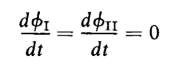
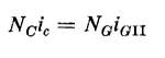
which is the same as in the case of the parallel connection of gate windings. Thus, when one reactor saturates, the flux through both cores remains constant, and we have
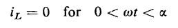
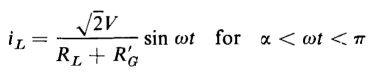
Because of symmetry, the saturation interval, or conduction interval, is the same, regardless of which reactor saturates under steady-state conditions. The load current, therefore, has the same wave form as for the parallel connection, i.e.
and
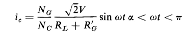
The a-c components of the fluxes in the two cores must therefore have identical wave forms, and, because of symmetry and by virtue of the polarities of the respective control windings, they are shifted by equal amounts, but in the opposite direction from the zero axis, just as shown in Fig. 7-9(b) for the parallel operation of gate windings. With the series connection, the instantaneous currents through the gate windings must at all times be equal to each other and to the load current. Since the mmfs on each core must be zero when both are saturated (during which interval the current in the gate windings is zero), the current in the control winding must also be zero. However, when one core is saturated, its control winding acts as a short circuit on the control winding of the other core, which is unsaturated, and, through transformer action, causes the voltage across the gate winding of the unsaturated core to be zero. The net mmf acting on the unsaturated core must be zero so the ampere turns in the control winding (secondary) must equal the ampere turns in the gate winding (primary). Hence, with core I saturated
and during the conducting interval the control current is
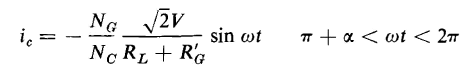
But a half cycle later core II is saturated, and the current in the control circuit is expressed by
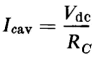
The wave forms of the load current, which is also the current in both gate windings and the current in the control circuit, are shown in Figs. 7-10(b) and 7-10(c). The average value of the control current is the d-c component that is determined by the resistance of the control circuit and the d-c voltage applied to the control circuit. Hence
where Rc is the resistance control circuit. The rms value of the control current is actually greater when the gate windings carry current, being
where Icac is the rms value of the a-c component in the control current. It is important to note that the a-c component in the control current does not equal the rms value of the gate current or output current referred to the control winding.
|
|||
| Home Saturable Reactors Operation With Free Even-Harmonics |
|
||
Last Update: 2011-01-10