| Radio Antenna Engineering is a free introductory textbook on radio antennas and their applications. See the editorial for more information.... |

|
Home  Low-Frequency Antennas Antenna Reactance Practical Flat-top Design Low-Frequency Antennas Antenna Reactance Practical Flat-top Design |
||||||||


|
  |
|||||||
|
Practical Flat-top DesignAuthor: Edmund A. Laport In low-frequency applications, Gν is always less than 90 degrees so that X α is always capacitive. The value of Gν is determined by the size of the antenna and has a dominant influence on its cost. The value of Z0 and X1 must therefore be minimized once the limits of Gν are determined economically and structurally.
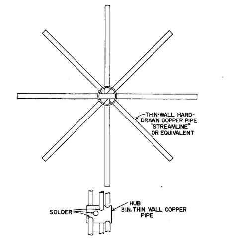
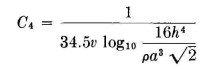
A cage of four wires in a square cross section is a desirable one from both mechanical and electrical standpoints for ordinary antennas. Its construction is relatively simple, the mechanical stresses are easily equalized among the wires, it has moderate wind resistance, and it gives the maximum increase in capacitance per unit length for practical spac-ings for the amount of copper required. For a square cage of four wires located a height h above ground, with wires of radius p spaced a distance a, the capacitance in farads per meter is
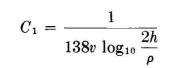
A single wire of the same radius at the same height has a capacitance of
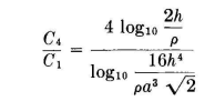
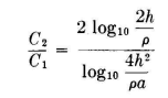
The ratio of the capacitance of the cage to that of the single wire is therefore
Figure 1.4A is a curve of this ratio for a particular case for a given height and wire size as a function of a. Figure 1.4B shows curves of the capacitance ratios for a particular height and wire size for cylindrical cages of various numbers of uniformly spaced wires and cage diameters. For two wires in parallel, spaced a distance a,
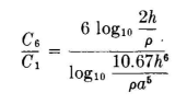
For a six-wire cage, the capacitance ratio is
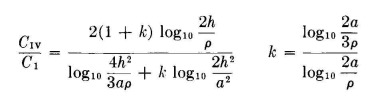
If one wishes to use four wires spaced a uniform distance a in a flat plane, the ratio of capacitance to that of a single wire can be obtained with the following equations, which include the solution for k, the ratio of charges on the two inner wires to those on the two outer wires:
To test the practical application of these principles, we can analyze an antenna of known characteristics to see how closely the computed values compare with the measured values.
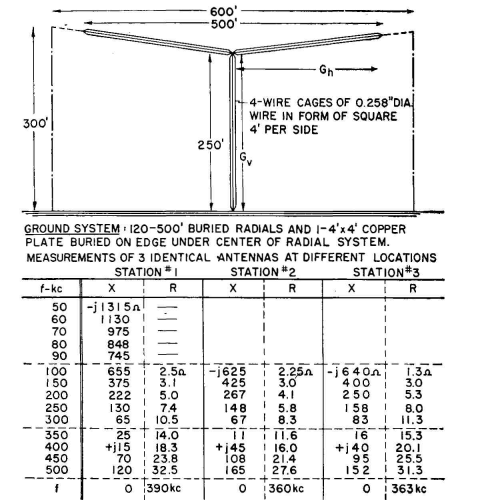
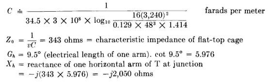
Identical Antennas at Different Locations. Consider the antenna shown in Fig. 1.5. Let us try to verify the reactance values at 100 kilocycles as measured at the three different locations. At the outset we recognize some important empirical factors not amenable to quantitative prediction, for instance, the end effect as the cages of the flat-top converge to a point, the capacitance of the insulators at the point of convergence, and the stray capacitance to the grounded supporting towers and to the supporting cables. At 100 kilocycles the vertical height is 9 degrees, and each arm of the flat-top will be 9 degrees plus an estimated additional 0.5 degree (5 percent. to account for all spurious end effects. Thus we consider each arm of the T (Gh) as 9.5 degrees. The entire system is a four-wire square cage of 0.129-inch-radius wires spaced 48 inches from each other. The average height of the flat-top is about 270 feet, or 3,240 inches. The capacitance per meter of the flat-top is then calculated.
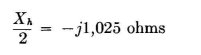
With the two arms in parallel, the total terminal reactance of the flat-top is approximately
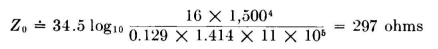
The characteristic impedance of the vertical cage, which we shall take at the mid-point (h = 1,500 inches) is of the order of
The input reactance at 100 kilocycles is computed to he, using Eq. (8), Chap. 4,
This compares with 625 ohms, 640 ohms, and 655 ohms measured values at the three stations. Apparently the end effect was correctly estimated. The reader may wish to compute the reactance of a single-wire antenna of the same dimensions.
|
||||||||
| Home Low-Frequency Antennas Antenna Reactance Practical Flat-top Design |
|
|||||||


Last Update: 2011-03-19