|
Structural Design
Author: Edmund A. Laport
Low-frequency antennas usually involve a great deal of mechanical engineering. In some cases the mechanical problems are more extensive than the electrical. For this reason the radio engineer often requires the aid of civil and mechanical engineers when design responsibilities exceed his normal competence. The design of supporting structures for radio antennas is now a special field of engineering practiced by those engaged in the business of supplying masts and towers. When these structures must support extended aerial wire systems many of the
mechanical problems are taken over by the tower engineers. Nevertheless the radio engineer should be familiar with certain elements of structural design in order to orient his preliminary antenna design toward forms that will be practical and economical. These elements are the same as those required for high-frequency antennas and transmission lines; therefore Sections. 3.26 and 4.13 should be consulted.
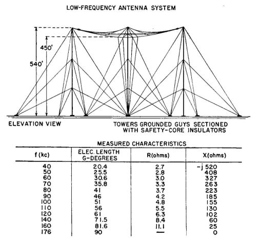 |
| FIG. 1.33. Triangular flat-top antenna (elevation). |
Various good examples of assembly details for low-frequency antennas are presented photographically in Figs. 1.35 to 1.43. These details will serve as a guide to good engineering practices for a wide range of applications.
The mechanical loadings on members of a low-frequency antenna are often rather large, and it becomes necessary to use high-strength conductors, even though electrical conductivity has to be sacrificed. It is customary to use stranded conductors of phosphor bronze, Calsun bronze, and copper-clad steel when exceptional strength is needed. Some high-strength alloys require great care in construction to avoid annealing during soldering, which reduces the strength. The same effect is obtained if the conductors are overheated by sleet-melting currents when current is allowed to flow long after the ice has been removed from the wires.
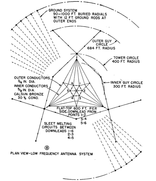 |
| FIG. 1.34. Plan view of antenna shown in Fig. 1.33. |
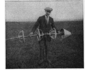 |
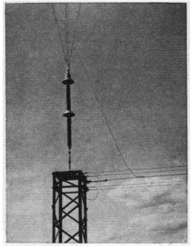
| FIG. 1.35. Assembly of two antenna strain insulators in series, both fitted with potential-grading rings and one with a rain shield. |
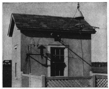 |
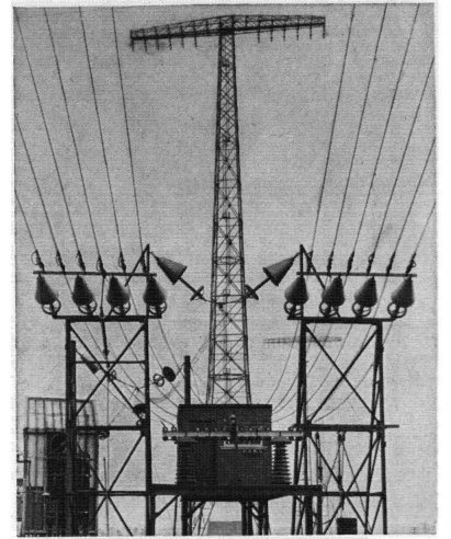
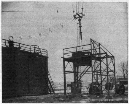
| FIG. 1.36. Antenna down-lead and coupling-house-entrance detail as used at medium-power low-frequency stations. |
 |
| FIG. 1.37. Antenna down-lead details for the Rocky Point, New York, high-power very-low-frequency multiple-tuned antenna. (Photograph courtesy of RCA Communications, Inc., and Drix Duryea.) |
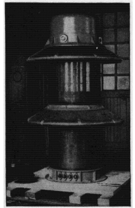 |
| FIG. 1.38. High-voltage oil-filled safety-core tower-base insulator with tower-lighting transformer inside the insulator. (Photograph courtesy of A. 0. Austin.) |
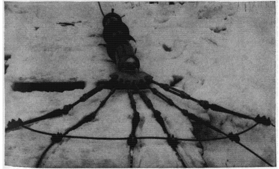 |
| FIG. 1.39, Detail showing the assembly of wires to the strain insulator at the corners of antenna flat-top system of antenna in Figs. 1.33 and 1.34. (Photograph courtesy of Royal Canadian Navy.) |
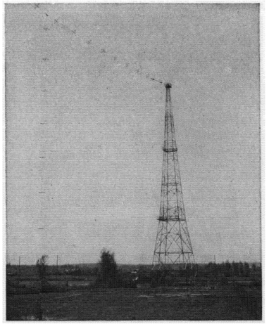 |
| FIG. 1.40, Four-wire cage T antenna built according to the dimensions of Fig. 1.5. (Photograph courtesy of Royal Canadian Navy.} |
 |
| FIG. 1.41. Down-lead insulator and the end of the six-wire unbalanced unmatched feeder for the antenna of Fig. 1.5. |
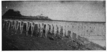 |
| FIG. 1.42. Example of heavy icing on an antenna wire. (Photograph courtesy of J. S. Hall and C. I. Soucy.) |
 |
| FIG. 1.43. Antenna down-lead detail for antenna built according to Figs. 1.33 and 1.34, showing down-lead counterweight and precautions at tuning-house entrance for large currents and high potentials. (Photograph courtesy of Royal Canadian Navy.} |
This also points out the reason why it is essential to design sleet-melting circuits so that ice is removed uniformly from all the conductors of the system in about the same time - otherwise some of the conductors may be overheated before ice is removed from others.
|

 Low-Frequency Antennas


