| Radio Antenna Engineering is a free introductory textbook on radio antennas and their applications. See the editorial for more information.... |

|
Home  Medium-frequency Broadcast Antennas Input Impedance in a Directive Array Cancellation of Mutual Impedances Medium-frequency Broadcast Antennas Input Impedance in a Directive Array Cancellation of Mutual Impedances |
||||||


|
  |
|||||
|
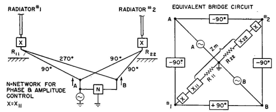
Cancellation of Mutual ImpedancesAuthor: Edmund A. Laport It is possible to feed such an array in a manner that will cancel mutual impedance. The principles are exemplified in Figs. 2.22 and 2.23. By simultaneously exciting both radiators with equal cophased currents and equal antiphased currents and with any arbitrary phase or amplitude relationships between these two pairs of currents, mutual impedance is balanced out, as shown in the vector diagram. Then any desired excitation of the radiators in phase and amplitude, to obtain any pattern that is possible with the chosen spacing between radiators, requires only power division and phasing between the two pairs of feeders, while the terminal conditions of the array remain constant at the inputs
A and B (Fig. 2.22). This method is useful where a variable pattern is required. In the vector diagram (Fig. 2.23) A1 and A2 (equal and in phase) are the currents in radiators 1 and 2 due to excitation by the A branch; B1 and B2 are the radiator currents due to antiphased excitation by branch B. The angle φ1 is the phase difference, and the amplitudes of B1 and B2 are the difference due to power ratio controlled by the network N. The relative amplitudes I1 and I2 and phase φo of the resultant radiator currents are seen to be controllable by varying φ1, A, and B. This can all be done with one network.
In this circuit the self-reactance of each radiator is canceled by the series reactance X, and the feeders are made with a characteristic impedance equal to the self-resistance of the radiators R11 and R22. The equivalent bridge circuit of Fig. 2.22 will aid in understanding what follows and shows why the generators A and B are mutually uncoupled and why the loads R11 and R22 are also mutually uncoupled. When the B side of the bridge is removed, the situation always seen by generator A is apparent, and vice versa. With B removed, A sees a load impedance of Z1 = Z11 + Zm because the currents in the two loads are cophased.
Now the relative phase and amplitude of currents from A and B can be changed at will without any reaction between them, and each sees a constant load. It is interesting to note that when A and B are equal and cophased, the current in radiator 2 is doubled and that in 1 goes to zero. Then all the power is in one radiator, and the array is nondirective. When equal and antiphased, all the power is in radiator 1. The power in the array is contributed by generators A and B. The amount of power from A is 2·IA2R11, and that from B is 2·IB2R11. The sum of these powers, less any losses in the feeders and network, is the total power input to the antenna array. Arbitrary line lengths other than 90 degrees can be used if building-out (or shortening) sections are inserted in each line to obtain the effect of 90-degree lines. Lines of characteristic impedance other than Z0 = R11 can be used if impedance-matching networks are inserted? in each feeder which have equal phase characteristics in the generalized case or are designed for zero phase shift of input and output currents when lines of 90 degrees length are used. This same circuit has application in the paralleling of synchronous transmitters without reaction, by making R11 the useful load and R11 a dummy load. Then when the transmitters are not perfectly cophased, nothing happens except that some power is lost in the dummy load. The phasing can be adjusted by observing the current through the dummy load, which will read zero when A and B are precisely equal in phase and amplitude. Under this condition, all the power from both generators is delivered to the useful load.
|
||||||
| Home Medium-frequency Broadcast Antennas Input Impedance in a Directive Array Cancellation of Mutual Impedances |
|
|||||

Last Update: 2011-03-19