| Radio Antenna Engineering is a free introductory textbook on radio antennas and their applications. See the editorial for more information.... |

|
Home  High-frequency Antennas Bandwidth of a Horizontal Half-wave Dipole High-frequency Antennas Bandwidth of a Horizontal Half-wave Dipole |
||||||||||||||||||||||||||||||||||||||


|
  |
|||||||||||||||||||||||||||||||||||||
|
Bandwidth of a Horizontal Half-wave DipoleAuthor: Edmund A. Laport
A dipole antenna, like any resonant circuit, has a certain natural selectivity. The selectivity is increased by any influences that reduce its radiation resistance, such as proximity to ground or other reflecting object.
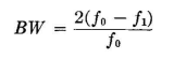
The selectivity is decreased by increasing the cross-section area of the dipole. The bandwidth is defined as that band of frequencies enclosing the frequency f0 (for which the system has matched impedances), where the feeder standing-wave ratio Q does not exceed some prescribed value, such as 1.41, which is the limit for 3-decibel response for the maximum side frequencies. The actual tolerance in standing-wave ratio throughout the bandwidth required for the emission employed governs the quality of the emission. The standards of performance desired must be taken into account in designing the antenna to accommodate the necessary bandwidth of emission.
This gives the point at which the response to the lower side frequency is down 3 decibels. The 1-decibel response values shown in Table 3.1 were interpolated.
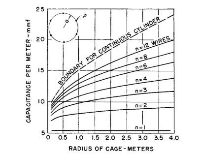
The rate of change of reactance with frequency for a center-fed horizontal half-wave dipole is much greater than the rate of change of resistance with frequency. For this reason, any means that will reduce the reactance variation rate will increase the intrinsic bandwidth of the dipole. Large-diameter conductors or a cage of small conductors will give increased bandwidths. Another method of broad-banding a dipole is to use the biconical cage (Fig. 3.27) or its two-dimensional analog, triangular sheets, or simulative wire arrangements. A cylindrical cage of wires is less effective than a continuous cylinder of the same diameter, as shown by Fig. 3.24, though for large diameters the cage is much the most practical to construct. Using Table 3.1 or Fig. 3.24 in conjunction with Figs. 2.15 and 2.16 (the resistances and reactances read from the latter must be doubled when applied to balanced dipoles), one can predict the dimensions to be used for a given bandwidth specification.
The use of a short-circuited stub of the order of one-quarter wavelength long connected across the terminals of a center-fed dipole will also increase its bandwidth. This stub should have a characteristic impedance substantially equal to the characteristic impedance of the half-wave dipole. This combination constitutes an open-circuited quarter-wave line (the dipole) in parallel with the short-circuited quarter-wave stub. Since both parts have the property of virtually opposite changes of reactance with frequency, the stub compensates the dipole in such a way as to maintain a more uniform terminal impedance for the feeder line over a range of frequencies enclosing the frequency for which the system has optimum impedance match. To center-feed a cage dipole, the inner ends of the side cages can be brought to a point by a conical taper. The length of the taper is important in its effect upon the impedance at the feed point. An optimum compromise is to make the length of the taper about 75 percent of the diameter. Many dipole arrays use half-wave dipoles end-fed from a balanced feeder. If the dipole impedance is to be resistive, the dipole must be shortened as its diameter is increased, owing to end effect. Figure 3.25 shows the proper length of a dipole which is a continuous cylinder, as a function of its diameter in electrical degrees for the case where the resistance is maximum and reactance is zero at one end. The ratio of electrical length to electrical diameter for maximum end resistance is given in Fig. 3.26. It is misleading to place any general values on the bandwidth of any antenna and feeder system. Bandwidth must be carefully computed or, preferably, measured (using scale models if necessary) for each particular application. The empirical conditions can then be accounted for more precisely. Hence, we only call attention to the means that can be employed to broad-band antennas for applications where bandwidth is a special consideration in the system design. The power-handling capacity of an antenna is increased by the same methods that increase bandwidth, and the two characteristics are interrelated. The bandwidth is increased as the potential gradients at the surface of the conductors decrease and as the peripheral charge density is decreased. Since the power-handling capacity of an antenna is limited primarily by pluming potentials, the reduction in potential gradients permits greater power input. In dipole arrays the total power input to the system is divided among several dipoles in some manner so that the power input to any one dipole is correspondingly lower. In high-frequency broadcasting it is sometimes desired to use a single dipole antenna or a pair of collinear dipoles for large power input. In such cases a cage dipole of large diameter or a biconical cage is a suitable antenna design, as shown in Fig. 3.27. In both cylindrical cage and biconical cage antennas it is desirable to use a ring connection to all of the wires at the end. Both types have relatively large bandwidth and power-handling capacity. For the same reasons, a folded dipole usually has greater natural bandwidth than a single-wire dipole. The folded dipole is an elementary cage antenna of two or three wires.
|
||||||||||||||||||||||||||||||||||||||
| Home High-frequency Antennas Bandwidth of a Horizontal Half-wave Dipole |
|
|||||||||||||||||||||||||||||||||||||
Last Update: 2011-03-19