| Radio Antenna Engineering is a free introductory textbook on radio antennas and their applications. See the editorial for more information.... |
|
Home  High-frequency Antennas Secondary Lobes Binomial Current Grading High-frequency Antennas Secondary Lobes Binomial Current Grading |
||||||||


|
  |
|||||||
|
Binomial Current GradingAuthor: Edmund A. Laport
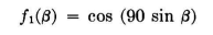
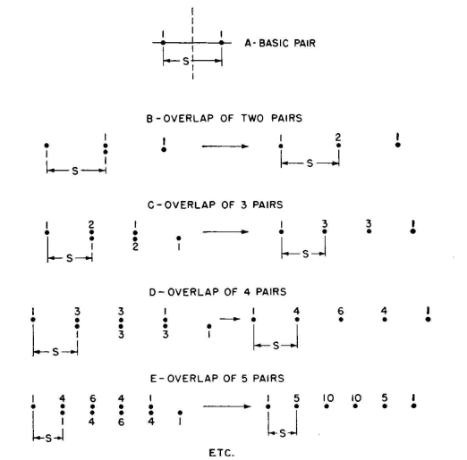
In order to retain the simplicity of half-wavelength elements with half-wavelength spacings between centers, a method of side-lobe suppression can be used where the current amplitudes are adjusted systematically along a line or a stack of dipoles. The simplest of these current-grading methods is that of symmetrical binomial current amplitudes. Figure 3.54 shows how these amplitudes are derived, using half-wavelength spacings, for a row of parallel dipoles. With a fundamental pair of identical parallel radiators with cophased and equal current amplitudes, and spaced one-half wavelength,
By overlapping two such pairs by one-half wavelength, there is the equivalent of three radiators in line with currents of 1 to 2 to 1 having the pattern
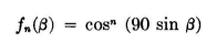
By continuing this procedure for n successive steps there results a row of n + 1 radiators with symmetrical current tapering from the center outward in each direction, the amplitudes being proportional to the values shown in Fig. 3.54. The array pattern will be
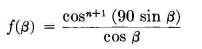
Any basic pair pattern may be used, and the principle is not limited to half-wavelength spacings as used in this equation. If the fundamental pair pattern is free of lobes, the patterns corresponding to successive powers of this pattern function must also be free of lobes and the beam increases in sharpness as the length of the array increases. The same effect takes place in a string of collinear dipoles, with center-to-center spacing of one-half wavelength, but the pattern has the additional directivity of the basic dipole pattern. In this case
The principal disadvantage of binomial distributions in practice is that the arrays become relatively large for a given beam width.
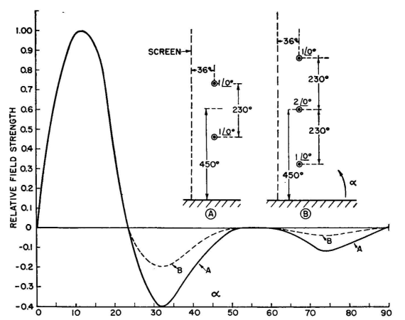
This is because of the very low current in the outer radiators, which have the greatest electrical spacing and normally contribute most to beam sharpness when uniform currents are employed. The reduction of currents in the outer radiators decreases their effectiveness from a gain standpoint so that a binomial array is much larger than a uniform array for the same sharpness of main beam. The latter, however, is attended with side lobes, as was seen from the study of such systems. An example of the application of the binomial current grading to a vertical pattern is the following: An antenna consisting of two stacked dipoles spaced 230 degrees, with a mid-height of 450 degrees and located 36 degrees from a passive reflector, has a secondary lobe at 32 degrees having a magnitude 40 percent of that of the main lobe. How can this lobe be reduced substantially? This vertical pattern has the equation through the main lobe
where the first cosine factor is that of the pair of stacked dipoles, the second sine factor that for the height of the mid-point of the array, and the third that for the screen reflector. All factors are functions of a\ hence any reduction in the value of any of these factors at any particular angle results in a proportional reduction in the value of the entire function. What would happen if the first factor, for the pair, were squared? A quick test can be applied for α = 32 degrees by comparing
According to this, squaring the pair factor reduces the lobe at 32 degrees to 48.5 percent of its present value, or to a value of 19.4 percent that of the main lobe, or better than 14 decibels below the field strength of the main lobe. This improvement may be very desirable. The next step is to determine the antenna configuration and current distribution that will give such a pattern. It is obtained by overlapping two identical pairs, giving a total of three dipoles in the stack, with their center located at the same point as the center of the original pair, and having a l-to-2-to-l distribution of current amplitudes, all cophased, and spaced 230 degrees between successive dipoles. The comparative vertical patterns for this array are shown in Fig. 3.55. It is instructive to interject at this point the application of binomial current grading to a type of array not heretofore discussed. It is a horizontal array of parallel dipoles arranged to give a desirable vertical pattern for low-angle concentration by spreading the array horizontally rather than vertically. At frequencies between 4 and 8 megacycles, vertical stacking of dipoles for a given low-angle beam quickly runs to great heights and becomes relatively expensive. The example to be discussed is an economical alternative, using more land but less height for a certain type of pattern suitable for long-distance transmission or reception. Consider the pattern for a pair of parallel radiators spaced 0.75 wavelength (270 degrees) and having a 45-degree phase difference. The equation for this pair is
This pattern can be read from the chart, Appendix IV-A, and the precise location of the nulls can be found from Appendix IV-B. It can be seen at once that this pattern, when squared, becomes unidirectional in the plane of the array with a narrow beam of large amplitude at high angle in the opposite quadrant.
It is now possible to introduce a height factor of such a value as to split this large, parasitic, high-angle lobe. As an exploratory step, let it be assumed that the height of the dipole plane (parallel to the ground) is one wavelength. The height factor therefore has nulls at 0, 30, 90, 150, and 180 degrees. The pair factor, raised to any power, has nulls at 59 and 146 degrees (counting the full semicircle from horizon to horizon in the vertical plane). Therefore, let the equation take the parameters mentioned so that it becomes
The pattern for this equation in rectangular coordinates is shown in Fig. 3.56. ´
This type of antenna is an end-fire array of three elements obtained by squaring the pair factor. The synthesis of the radiators and current distribution for obtaining this pattern results in the following: Number of horizontal radiators 3 Spacing between radiators 270 degrees Current distribution, progressing in the direction of the main lobe: 1.0 at angle 0 degrees 1.82 at 22 1/2 degrees 1.0 at 45 degrees The horizontal pattern for such an array includes the pair factor squared and the directivity factor for the number of dipoles used in line. The height factor is of course not involved in the horizontal pattern. An interesting fact to mention in connection with end-fire arrays generally is that their vertical and horizontal patterns are interdependent, and not separately controllable as with broadside dipole arrays.
|
||||||||
| Home High-frequency Antennas Secondary Lobes Binomial Current Grading |
|
|||||||


Last Update: 2011-03-19