| Radio Antenna Engineering is a free introductory textbook on radio antennas and their applications. See the editorial for more information.... |

|
Home  High-frequency Antennas Long-wire Antennas Long Wires as Directive Antennas for High Frequencies High-frequency Antennas Long-wire Antennas Long Wires as Directive Antennas for High Frequencies |
||||||||||


|
  |
|||||||||
|
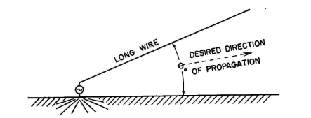
Long Wires as Directive Antennas for High FrequenciesAuthor: Edmund A. Laport The intrinsic directivity of a single long-wire radiator makes it useful for some elementary applications. The presence of ground beneath the antenna modifies its pattern, of course, the extent of modification depending on the height above ground and its orientation with respect to ground. In such applications, the main lobe resulting from direct and image radiations is focused in the direction of optimum propagation to the desired distant receiving point, and the other lobes fall where they will. Interference between direct and image radiations causes some of the parasitic lobes to be reduced or canceled and others to be reinforced. The orientation of the wire with respect to the propagation path and ground determines the polarization of the wave transmitted (or received) on the main lobe of the pattern.
The symmetry of lobes in the radiation pattern from a standing-wave antenna gives a bidirectional radiating system. The system is excited unbalanced against ground, and for this reason a radial ground system of wires slightly above, on, or beneath the ground is necessary to avoid terminal ground losses.
An equivalent form of antenna using a traveling-wave current distribution is shown in Fig. 3.71. This is in all respects the same as Fig. 3.70 except that the end of the wire is terminated so as to suppress reflections from the outer end and thus to suppress standing waves. A free end that is one-quarter wavelength long gives an impedance at its inner end that is very low with respect to the characteristic impedance of the system at some chosen frequency of operation. This permits the insertion of an impedance Zt which is given a value equal to the characteristic impedance of the system. This termination must dissipate all the power that would otherwise be reflected if the system were not so terminated. The radiation pattern for this system is essentially unidirectional.
The presence of the terminating impedance naturally decreases the selectivity of the system, because the impedance of the open-ended quarter-wave projection will remain low with respect to the impedance Zt over a band of frequencies on each side of that at which it is resonant. By making the characteristic impedance of the quarter-wave projection lower than that for the remainder of the system, the bandwidth of the system as a whole can be increased further when necessary. If still wider bandwidth termination is wanted, two or three mutually perpendicular projections can be used at the end which are resonant to different frequencies within 3 or 5 percent of the mean frequency. Resonating in turn over the band, the projections serve to maintain a low impedance at the outer end of the impedance Zt and so maintain a more constant termination impedance over a band of frequencies. As in all traveling-wave systems, it is advantageous, for improved transmitting radiation efficiency, to use a low characteristic impedance so that the antenna current will be a maximum for a given power input. Experiment has shown that the correct termination of a long wire in this manner requires a complex impedance and not solely a resistance. The terminal impedance for suppressing standing waves is not a constant value but varies with the length of the wire. The terminal impedance is of the type R + jX. The inductive reactance can be obtained from the extension wire by making it longer than one-quarter wavelength. This means that the correct resistance, determined by experiment, must also be located in the correct place along the wire, and that the correct location is more than one-quarter wavelength from the end of the wire. The resistance has an order of magnitude of 400 to 600 ohms in many cases, and 500 ohms is suggested as a starting value for the trials when the antenna consists of a single wire. The reactance values required usually lie between j150 and j250 ohms, so that, with a thin wire, the extension would be somewhere around 105 degrees long. Correct termination is best indicated by measuring the current distribution in the wire with inserted ammeters or a sliding ammeter inductively coupled to the wire. The distribution is complicated until the final correct termination is obtained; hence observations of current distribution should be made at several points along the entire length of the antenna. Horizontal polarization is generally preferred in high-frequency transmission. The same techniques described in the two preceding cases can be applied to systems that transmit or receive horizontally polarized waves. The same long wires are then placed parallel to the ground, but at an angle to the desired direction of propagation equal to that shown in Fig. 3.67A for the angle θm between the wire and the first lobe maximum. The same lobe on the other side of the wire will also be present when a single wire is used this way, and this is a major disadvantage. If a standing-wave excitation is used, there will also be two main backward lobes. This explains why antennas of this form are very seldom used. However, it is possible to use two parallel horizontal wires carrying traveling waves to cancel one major lobe and reinforce the other. The radiation pattern then contains one main beam and the usual multiplicity of minor lobes. The plan view of an antenna of this type is shown in Fig. 3.72. The two wires are excited in phase opposition, so that they are balanced to ground. The same end details are used as in Fig. 3.71, to suppress standing waves.
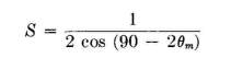
The ends of the wires are staggered so as to form an angle 90 - θm with the direction of the two parallel wires, in order to eliminate the other major lobe. The distance between wires as measured between the staggered ends is made equal to
For example, if the lengths of the wires inside of the terminating resistors Zt were 5 wavelengths, the angle θm would be 22.5 degrees. The stagger in the ends of the two wires would be 67.5 degrees with respect to the wire direction, and the spacing would be 0.707 wavelength.
|
||||||||||
| Home High-frequency Antennas Long-wire Antennas Long Wires as Directive Antennas for High Frequencies |
|
|||||||||


Last Update: 2011-03-19