| Radio Antenna Engineering is a free introductory textbook on radio antennas and their applications. See the editorial for more information.... |

|
Home  High-frequency Antennas Long-wire Antennas Long Wires with Traveling Waves High-frequency Antennas Long-wire Antennas Long Wires with Traveling Waves |
||||||||


|
  |
|||||||
|
Long Wires with Traveling WavesAuthor: Edmund A. Laport If it were possible to excite a long, straight wire in free space so that there would exist on it a pure traveling wave of constant amplitude and uniform phase difference for all elements of length, the radiation pattern would possess the following general characteristics:
As the length of the wire increases, the direction of the main lobe is pressed closer to the direction of the wire. It cannot ever approach the direction of the wire and in practice is never used closer than 15 or 17 degrees from the direction of the wire.
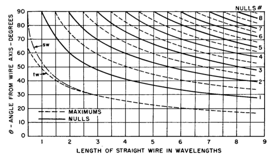
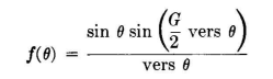
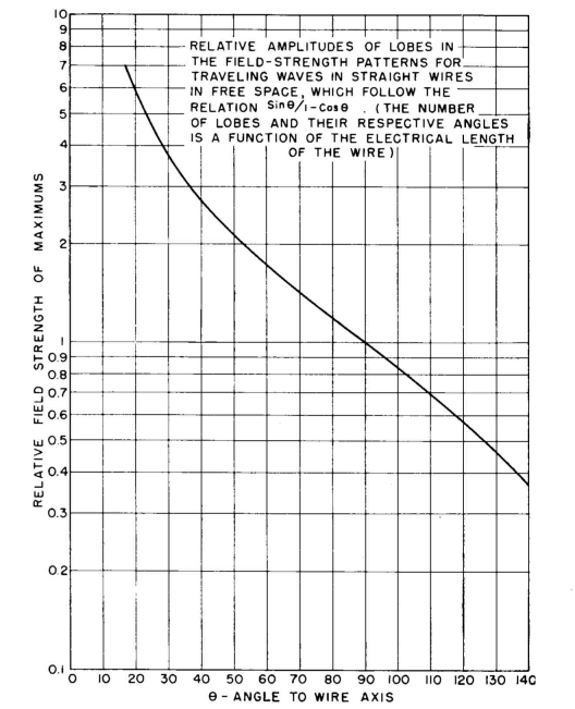
The complete pattern for a pure traveling-wave current distribution in a straight wire in free space can be quickly constructed with the aid of Figs. 3.67A and 3.67B. Figure 3.67A provides the angles of the maximums and nulls; Fig. 3.67B provides values for the successive maximums. When these points are plotted in rectangular coordinates, the function can be sketched with a fair degree of accuracy through these points. The accuracy is increased if cognizance is taken of the fact that the direction of the field is reversed in successive lobes, using positive and negative values alternately to represent their amplitudes. The shape of the field-strength pattern for a straight wire in free space carrying an unattenuated traveling wave of current may be found from the equation
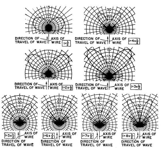
where versine θ = 1 - cos θ and G is the electrical length. Some patterns from this equation for lengths from λ/2 to 4λ are exhibited in Fig. 3.68. With the exception of the angle of the maximum in the dominant lobe for a wire less than three wavelengths long, the angles of nulls for both standing-wave and traveling-wave distributions are the same.
The difference between the patterns for the two different types of waves rests wholly in the amplitudes of the successive lobes. It is seen from Figs. 3.68 and 3.69 that the pattern for the traveling-wave tends to be unidirectional, since the envelope for the successive lobes is cardioidal. This fact gives special value to the use of traveling waves for excitation of long wires where a unidirectional characteristic is desired. Otherwise, the number of lobes and nulls being the same for both fundamental forms of excitation of long wires, there is the common characteristic of a radiation lobe for each half wavelength of wire. The multiplicity of lobes inevitably present when the wire is sufficiently long to give extreme directivity in the main lobe is one of the principal disadvantages of long-wire antennas. When long wires are used as elements of radiating systems, as in rhombic and V harmonic-wire antennas, there are many parasitic lobes extending in many directions. These parasitic lobes limit the directivity of an array made up of long wires. However, the economy and structural simplicity of long-wire antennas have given them great popularity, in spite of their faults with regard to parasitic lobes. These faults must be kept in mind in applying them practically.
Figure 3.66 also suggests that, in a practical system having some traveling wave and some standing wave, the angles of the nulls would remain constant but that the nulls would degenerate to minimums and the maximums would tend to asymmetry as the ratio of traveling wave to standing wave increased. Also, the angle of the first maximum would be tilted more and more toward the wire as the amount of traveling wave present increased. Indeed, this was already evident in Fig. 3.23.
|
||||||||
| Home High-frequency Antennas Long-wire Antennas Long Wires with Traveling Waves |
|
|||||||
Last Update: 2011-03-19