| Radio Antenna Engineering is a free introductory textbook on radio antennas and their applications. See the editorial for more information.... |

|
Home  High-frequency Antennas Horizontal Rhombic Antenna Stereographic Charts for Rhombic Antennas High-frequency Antennas Horizontal Rhombic Antenna Stereographic Charts for Rhombic Antennas |
|||||||||||||||||||||||||||||||||||||||||||||||||||||||||||||||||||


|
  |
||||||||||||||||||||||||||||||||||||||||||||||||||||||||||||||||||
|
Stereographic Charts for Rhombic AntennasAuthor: Edmund A. Laport The rhombic antenna, in common with all long-wire antennas, has an intrinsically complicated radiation pattern that is difficult to visualize without very extensive and laborious computation for each working frequency.
To obtain a main beam of desired orientation and desired width and height, and to minimize undesired lobes in many other orientations, it is necessary to have a method for observing quickly the effects of varying any single parameter in relation to all the others. This is obviously impossible by any system of numerical computation but is practical, and in fact easy, by the graphical method described by Foster
Each lobe of radiation from each leg of a rhombic consists of a cone of revolution around the wire. The stereographic projection of the maximum value of one of these cones is a portion of a circle. There will be one such cone of radiation for each half wavelength of the length of each leg.
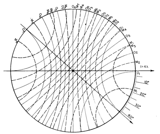
Between successive lobes of radiation are cones which show the locus of intervening nulls. The stereographic projection of a four-wavelength leg of a rhombus is shown in Fig. 3.83. The cones of maximums (shown as broken lines) and the cones of nulls (shown as solid lines) appear in sequence with half of the maximums in the forward half of the hemisphere and the other half in the rear quadrant, reckoned with respect to the direction of current flow in the wires. In other words, in the forward half of the hemisphere there is one maximum per wavelength of each leg. The same is true of the rear half, when each leg is an integral number of wavelengths long. This chart locates the stereographic coordinates of the cones of maxi-mums and nulls but does not show the magnitudes of the successive maximums.
Two such charts can be overlaid and set at an angle equal to that of the acute angle of the rhombus to show the pattern for the entire rhombus in free space. Figure 3.84 shows such a combination when the acute angle is 42 degrees with a leg length of four wavelengths. This figure reveals all the null regions in the three-dimensional pattern because each null line for each leg produces a null in the final pattern. Any radiation that occurs must be a lobe of radiation peeking out through each area enclosed by the solid null lines. Strongest radiation occurs where the first maximums (M1) for the two sides cross. This becomes the main beam and occurs along the major axis of the rhombus, which is the angle that bisects the acute angle of the antenna. Figure 3.67B shows that, for a traveling wave on a straight wire, the field strength of each successive lobe diminishes in magnitude. Therefore successive maximums for each side of the rhombus diminish in magnitude, so that the lobe formed where two second maximums (M2) cross will be less than for the main beam, and likewise where the first maximum for one leg intersects the second maximum for the other leg the resulting lobe will also be smaller. The relative magnitudes of these other lobes where successive maximums intersect, with respect to the main beam, are given in Table 3.2.
When the rhombus is placed with its plane parallel to ground, its height produces another interference pattern with the image in the same manner as a horizontal dipole. Figure 3.16 shows where the nulls and maximums occur as a function of the height above ground. In stereo-graphic projection, each such maximum and each such null will appear as a circle concentric with other altitude circles as discussed in connection with Fig. 3.83. As an example consider the rhombus of Fig. 3.84 and place it 1.18 wavelengths above ground. Figure 3.16 shows that this will put maximums of relative magnitude 1.0 in the height factor at vertical angles of 12.5 and 39.5 degrees and nulls at angles of 25 and 57 degrees. When these values are applied to Fig. 3.84, we obtain Fig. 3.85. This latter figure is marked to show the locations of the maximums of the main beam and several minor lobes. The azimuth of each lobe from the rhombic axis can be measured with a protractor, and the elevation angles are represented stereographically. The design represented in Fig. 3.85 is an optimum for a horizontal rhombic antenna having four wavelengths per leg. The term "optimum" is based on the following considerations: The crossing of first maximums for the legs coincides with a maximum in the height factor. The crossing of the first maximum for one leg with the second maximum for the other leg coincides with a null in the height factor, so that these lobes are split and reduced to small residual pairs of lobes.
The first maximum for one leg intersects with the third maximum for the other leg at zero degrees elevation, where it is canceled by a zero in the height factor. Smaller residual lobes at higher angles do exist, however. It will be seen that at the lowest angles the higher-order lobes do not meet so that their magnitudes are greatly reduced compared with those which would result from a different apex angle which would permit them to intersect. The intersections of maximums at higher angles cannot be suppressed, but they are intrinsically of small magnitudes. The intersection of second maximums along the array axis is at a relatively high angle (47 degrees) and is reduced from normal magnitude by the diminishing value of the height factor at this angle. Therefore the pattern for this system is an optimum because all spurious lobes are minimized and the main beam is maximized.
Let it be assumed that this optimum-design antenna for the frequency corresponding to these electrical parameters is to be constructed; but now it is desired to investigate the performance of this same antenna at another frequency for which the horizontal rhombic antenna has a leg length of 7 wavelengths. The physical dimensions therefore remain fixed, while the frequency is increased in a ratio of 7 to 4. The electrical height at this frequency will be 2.06 wavelengths. The result is shown in Fig. 3.86, from which it is obvious that a very unsatisfactory pattern is obtained. The main beam is split, and some of the spurious lobes will have magnitudes as great as, perhaps even greater than, the main lobe. Also, the main beam is excessively sharp horizontally; yet in spite of this sharpness the gain must necessarily be very low.
The energy of the system is leaking out through other lobes in other directions rather than being concentrated in the main beam. It might be difficult to discover this situation by arithmetical computations, but it is quickly observed by the use of stereographic charts. The data for Fig. 3.81 were derived on the basis of conditions corresponding to Fig. 3.85. Abbreviated charts of this type can be prepared very quickly if information is wanted only for the first two or three maximums, instead of for the entire pattern. With the aid of Fig. 3.67A, a pair of stereo-graphic charts can be drawn on tracing paper in a few minutes. These may then be used directly to ascertain the antenna parameters for optimizing the main beam or manipulating the spurious lobes of major importance, as shown in Fig. 3.87. The same design charts can be used for horizontal-V and inverted-V antennas. A single chart can be used to determine the patterns for other forms of long-wire antennas parallel to ground. Table 3.2 shows that the magnitudes of secondary lobes formed by intersections with the first maximum for one side diminish slowly. Such lobes usually occur at the lower altitude angles in the forward half of the hemisphere and are bunched around the main beam. When these large secondary lobes occur at angles higher than that of the main beam, the height can be adjusted to diminish or split them. Unfortunately these large lobes often occur at the sides at altitude angles the same as or lower than the main beam so that the adjustment of the height factor has no selective controlling influence. The application of the stereographic charts for the rhombic antennas enables one to select easily an optimum design for one electrical size of antenna. One can see how the main beam may be broadened, narrowed, raised, or lowered and how the height may be used to control the vertical-plane pattern along the major axis, and in fact in many other directions. When the geometry and height are thus determined for one frequency, the same geometry may be used with corresponding changes in electrical length (using other charts) for other frequencies and the performance studied. If the pattern is found to be undesirable at some frequency, trial and error is used until acceptable compromises are found for a series of working frequencies. Such graphical computations show the conditions to be expected as different charts are used for different leg lengths corresponding to different working frequencies. One of the dangers associated with blind formulas and design charts for rhombic antennas is that they usually give insufficient information for an optimum selection of parameters and do not indicate reasonable working frequency limits. Figure 3.81 was computed using stereo-graphic charts where the most important secondary lobes were considered. The optimum design minimizes the first side lobes for maximum gain and gives the cleanest horizontal and vertical patterns. In regular engineering practice a series of charts are drawn on tracing cloth, following Foster's method. These may be, for example, for two, three, four, five, six, and seven wavelengths per leg. Those who have a great deal of rhombic-antenna designing to do may want charts for intermediate lengths. Charts carefully constructed in a circle of 10 centimeters radius are of a very convenient size. Positive transparency films can then be made from the originals by photographic contact printing with cut film sheets or by various copy processes that make direct positives on clear plastic sheets. A pair of positive transparencies for each leg length are then set together at the angle chosen for best performance. A pair may be set together at a chosen angle with transparent adhesive tape and the combination reproduced by black-line, blueprint, or photographic contact printing to give a work sheet for a thorough analysis of the pattern, as well as for record purposes. It must be mentioned that all the foregoing is based on idealized conditions - that is, no attenuation of the traveling waves in the antenna, no standing waves whatever due to reflections from the far end or from the side corners, no effects from supports - and it assumes perfectly conducting ground. Because there is radiation from the system, there will be attenuation of the traveling waves. Attenuation causes the nulls to become minimums and the relative values of the maximums to be modified somewhat. However, attenuation does not alter the angles of the maximums and the minimums in the pattern. Then, it is practically impossible to eliminate some small amount of standing wave from the system, either at the termination or at the side corners. The presence of standing waves causes the magnitudes of the smaller lobes, especially those in the rear half of the hemisphere, to be increased. An appreciable amount of reflection may give some of the backward lobes, usually negligible, a considerable magnitude. The effect of imperfect ground fills out the nulls in the height factor and diminishes the maximums. However, all these effects are regarded qualitatively among other unavoidable imponderables and tolerances. It is especially important to emphasize at this point that the remarks made here concerning "optimum" rhombic-antenna designs mean optimum only in the sense of the best intrinsic radiation performance as an abstract matter. It would obviously not be an optimum antenna from an application standpoint if the antenna pattern was not optimum for fitting the propagation conditions. To make this perfectly clear, consider the following situation: You have made an analysis of the requirements for a given radio path from the ionospheric data and find that the optimum working frequency (or the nearest available assigned frequency) will permit communication over a sufficient number of hours per day if the angle of fire is 4 degrees; and it is further found that, for the same path, angles of fire higher than 12 degrees will penetrate the ionosphere and be lost during a substantial percentage of the time. The antenna that must be used for this path therefore is one with the main beam aimed 4 degrees above the horizon. Upon examination of Fig. 3.81, it is noticed that the optimum parameters given do not fit the applicational requirements because the beam angles are much higher than can be used, and the resulting beam angles for the optimum parameters are very near to those which penetrate on the path under consideration. It is evident from this example, which typifies the kind of problems encountered in antenna applications, that what is optimum from a purely antenna viewpoint is not necessarily optimum from the communication-engineering viewpoint. To adapt an antenna to this particular requirement, it will be necessary to abandon Fig. 3.81 as a source of design data and to seek another design that gives the proper angle of fire to fit the propagation requirements. The rhombic-antenna design ultimately selected to do this will not then be an "optimum" in the sense represented by Fig. 3.85, but it will be an optimum design for the actual radio circuit. If an "optimum" rhombic were to be applied to this case, the antenna would perform well as an antenna but the radio circuit would be unsatisfactory for a large percentage of the time. It must be explained further that Fig. 3.81 does in fact have great practical utility because the angles of fire for the optimum rhombic-antenna designs will be optimum for a large percentage of actual radio circuits. When angles of fire lower than those shown in Fig. 3.81 are required, the main beam can be lowered by increasing the acute angle of the rhombus by a small amount; but this angle should never exceed a value somewhat smaller than twice the angle of the cone of first maximum with respect to the wire for one of the legs. In other words, the acute rhombus angle should never quite equal twice the angles given in Table 3.5 in connection with the inverted-Y antenna. Otherwise the main beam will split. If the main beam angle is lowered by changing the acute angle, it is also necessary to increase the height of the rhombus to bring the first maximum in the height factor at the best angle of fire computed for the radio path. When this is done, the antenna pattern is matched to the radio path and will produce the best results operationally. This discussion brings out what has been said before about antenna "gain" being a purely incidental factor in antenna applications for practical communication, and not a primary objective in antenna design. Unless the gain is effective in the required direction to fit the radio path, it is virtually meaningless. The design for the antenna is one problem, and the design of the radio circuit is quite another. The design of the radio circuit includes the propagation analysis and also the characteristics of the receiving antenna. There is a large accumulation of data and experience which shows that the transmitting and receiving antennas should be complementary and possess identical patterns. The dominant angle of arrival of signals has been proved to be essentially the same as the optimum angle of fire for the path when the transmitting antenna is matched to the radio path. If the receiving antenna also has maximum response to this dominant angle, the results are maximized by two effects - first, the two antennas do not work against each other from the standpoint of angular response; and second, the signal stability is maximum because normal variations in layer height, which cause variations in the optimum fire angle, occur symmetrically with respect to the average angle obtained from the monthly averages given in the ionospheric propagation data. A variation of 2 degrees, for instance, in fire angle gives relatively small variations when this occurs around the peaks of the main lobes, whereas the same angular variation taking place along the underside of the main lobes of both transmitting and receiving antennas, where the response is changing very rapidly with angle, can introduce many decibels of fading unnecessarily. These remarks relating to the matching of the antenna patterns to the radio path are quite general and do not apply only to the application of rhombic antennas. They are included in this section for this important reason - rhombic antennas are very likely to be used for a wide range of working frequencies, while the antenna itself is correct for only a very narrow band of frequencies around the desired optimum. One may design for one optimum condition and then proceed to let other working frequencies fall where they may, even though they are very far from optimum. The scarcity of available frequencies and the need to make the best possible use of assigned frequencies will certainly require the communication engineer to place optimum performance ahead of capital economy if the latter depreciates performance on other working frequencies for which the system is not optimum. When this occurs, as it often does, there is a tendency to use greater transmitter power to make up for antenna deficiencies. This, of course, causes unnecessary interference and offers little improvement in circuit operation. In the long run there may be economy in using a separate specially designed antenna for each frequency on each path. The rhombic antenna is very economical when, and only when, its characteristics at different specific working frequencies are well matched to the propagation medium. Rhombic receiving antennas designed for low-angle reception inevitably have a narrow main horizontal lobe. Care must be taken not to employ designs having patterns that are too sharp to accommodate the normal range of signal variations in both vertical and horizontal planes. One advantage mentioned for the rhombic antenna is the ease with which the antenna can be changed in height from season to season or year to year as propagation conditions change through the annual and the sunspot cycle. In planning a system, consideration may well be given in this respect to the height of the supports so that the antenna can be raised and lowered to use the optimum height from one extreme to the other.
|
|||||||||||||||||||||||||||||||||||||||||||||||||||||||||||||||||||
| Home High-frequency Antennas Horizontal Rhombic Antenna Stereographic Charts for Rhombic Antennas |
|
||||||||||||||||||||||||||||||||||||||||||||||||||||||||||||||||||


Last Update: 2011-03-19