| Radio Antenna Engineering is a free introductory textbook on radio antennas and their applications. See the editorial for more information.... |
|
Home  High-frequency Antennas Fishbone Receiving Antenna High-frequency Antennas Fishbone Receiving Antenna |
|||||||||||||||||||||||||||||||||||||||||||||||||||||


|
  |
||||||||||||||||||||||||||||||||||||||||||||||||||||
|
Fishbone Receiving AntennaAuthor: Edmund A. Laport
The principles of the Beverage wave antenna were first applied to high-frequency reception in the form of the fishbone antenna. Two forms of this antenna have been evolved in the United States and England, both intended for the reception of horizontally polarized waves.
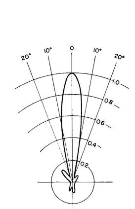
Fishbone antennas may be used in various arrays, according to the directivity patterns desired. The one commonly used consists of two fishbones in broadside using common intermediate supporting structures. Typical patterns for single- and two-bay fishbones are shown in Figs. 3.93 and 3.94. The two-bay design unites the transmission lines symmetrically and the main line to the receiver is then of one-half of the antenna characteristic impedance. For this purpose it has been the practice to employ the four-wire cross-connected balanced type of line, a picture of which is shown in Fig. 4.95.
Constructional dimensions for fishbone antennas for various ranges of frequencies in the high-frequency band are given in Table 3.4. The measured performance of fishbone antennas compares closely with that of a rhombic antenna having the same main beam orientations even
though the former occupies a much smaller land area. The fishbone pattern is relatively free of secondary lobes and the corresponding parasitic directional responses.
The number of dipoles used is sufficient to produce the effect of smooth continuous loading of the central feeder. This requires seven or more per wavelength, the wavelength in this case being that in the feeder at the wave velocity employed. Another version of the fishbone antenna is diagrammed in Fig. 3.95. The dipoles in this system are one-half wavelength long at some chosen frequency and omit the series capacitors. They are spaced at one-quarter-wavelength intervals along the feeder. In all other respects the performance and structural characteristics resemble those of the RCA fishbone. The fishbone antenna is one of the preferred forms for wide-band response in the high-frequency fixed services. Its higher cost in many cases is offset by the smaller land area required as compared with an equivalent horizontal rhombic antenna.
|
|||||||||||||||||||||||||||||||||||||||||||||||||||||
| Home High-frequency Antennas Fishbone Receiving Antenna |
|
||||||||||||||||||||||||||||||||||||||||||||||||||||


Last Update: 2011-03-19