| Radio Antenna Engineering is a free introductory textbook on radio antennas and their applications. See the editorial for more information.... |
|
Home  High-frequency Antennas Construction of High-frequency Antennas High-frequency Antennas Construction of High-frequency Antennas |
||||||||||||||||||||||||||||||||||||||||||||||||||||||||


|
  |
|||||||||||||||||||||||||||||||||||||||||||||||||||||||
|
Construction of High-frequency AntennasAuthor: Edmund A. Laport
Figures 3.97 to 3.123 are included to provide detailed information on various aspects of mechanical construction of high-frequency antennas. The figures show both low-power and high-power techniques that have been employed successfully in systems originated by many different engineers, together with various forms of supports.
These are but a few of the myriads of details that have been evolved throughout the world during the years of antenna development.
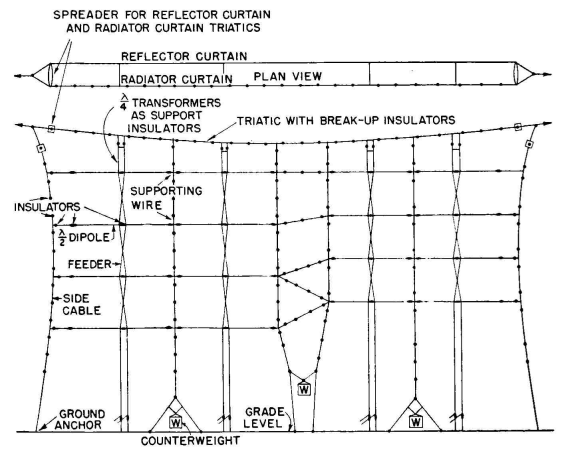
The simplest antennas are rigged between the masts with the active conductors supporting their own weight and that of associated feeders as in Fig. 3.97. The more extensive arrays employ triatics, from which the actual antenna assembly is suspended. Most of the mechanical stress is placed on the triatics, thus reducing the mechanical stresses on the active electrical elements and permitting more accurate dimensioning of radiators and feeders. This eliminates sags and provides better mechanical stability, which in turn gives better electrical stability. Radiator and reflector curtains are usually hung from parallel triatics, using spreaders to maintain the correct spacings between curtains. Conservative design calls for a minimum factor of safety of 2 on the principal tensioned members, such as the suspension triatics and halyards, under conditions of maximum wind and ice loadings. The automatic maintenance of predetermined safe tensions in such members is afforded by the use of counterweighted structures. The computation of simple catenary suspensions with uniformly distributed loadings is the same as that for transmission-line construction,
and formulas are given in Chap. 4. The localized equivalent weight of feeders and other loadings on a simple catenary (such as a single horizontal dipole antenna with a two-wire feeder connected at the middle of its span) modifies the problem to that of the catenary with a central loading equal to the downward pull of the feeder due to its own weight, the static pull of the ground anchor, and the wind and ice loadings. An approximate method for computing the catenary tensions for center-loaded triatics when the center loading is large with respect to the weight of the triatic proper is the following: Consider the weight of the triatic material lumped at the center of the span and added to the total suspended weight at the center to obtain the total center loading. Consider that a right triangle is formed by one-half of the span and the sag and the straight line drawn from tip to tip of the masts. Let A be the angle between this line and that of the stressed triatic in the loaded state when the sag is a chosen or specified value. If W is the equivalent total weight of the load at the center, then the tension of the triatic is
where T and W are in identical units. When the suspended load is more or less equally distributed along a primary triatic, this distributed loading is added to that of the weight of the triatic proper and the tension is computed as for a catenary triatic of that total weight W. Assuming the catenary to be firmly attached to the top of the mast, the horizontal pull P on each mast is
and the vertical compression load C on the mast is
When two triatics are used, one for a radiator curtain and one for a reflector curtain, but joined to a common halyard near the tower, their combined stress appears in the main halyard. If the halyard runs down the axis of the tower, the halyard stress is transferred to a compression load on the tower. If the halyard is anchored to ground at some distance from the tower base away from the antenna side, the compression load due to the antenna is reduced in accordance with the relation
where B is the angle between the halyard and the tower axis. A counterweight in the main halyard is desirable as a means for maintaining uniform tension with transient wind and ice loadings on the antenna system. In small lightweight antenna systems, built for economy, the tension can be released manually at a winch when occasional heavy wind and ice loading is present. In hurricane areas, where complete ability to withstand the extreme conditions would require extravagant structures, one may decide to use light inexpensive construction and expect occasional damage to the system on the theory that its replacement would be a more tolerable expense. Except for the very simplest structures, the precise computation of stresses in various parts of the antenna rigging becomes very complicated and often indeterminate. One may then use approximate methods, according to one's ingenuity, or resort to estimates. The uncertainties are allowed for in the safety factors, or "ignorance factors." When insurance against these uncertainties leads to considerable expense, guiding dynamic-tension measurements can often be made with the aid of mechanical scale models of the antenna.
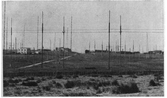
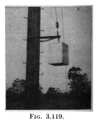
Such a scale model must accurately simulate distributed weights and all dimensions. Ice loadings can be simulated by judicious distribution of weights on various portions of the model. Wind stresses can be simulated by means of springs or elastic rubber which deforms the assembly by the specified amount correspond-ing to the wind pressures against the projected areas. Wood poles, similar to those used for telephone and power-distribution line construction in a large part of the world, are most frequently applied to the duty of supporting high-frequency antennas when they can be made of sufficient height. Round wood poles can sometimes be obtained in lengths of 70 or 80 feet, and occasionally longer. The length that must be underground depends upon the soil resistance and the guying provisions. Sometimes poles are set in concrete and sometimes not. They have to be set with the aid of a crane since they are too heavy to be erected with pikes. Figure 3.115 shows an assembled steel mast being erected in this way. Figure 3.120 shows the use of single high poles for rhombic antennas.
Shorter poles may be spliced in different ways to obtain wood supports of moderate heights. Figures 3.112 and 3.113 show the operations for lap-splicing two large poles. Figure 3.114 shows what has come to be called the "A" pole splice, and Fig. 3.111 shows a butt splice. Poles spliced in this way can be seen in Fig. 3.110. A wood mast fabricated from structural timber can be seen in Fig. 3.122. The advantages of wood in some regions of the world include relatively low cost, easy handling in construction, and the convenience of having a wide variety of standard items of assembly hardware available. The disadvantage of wood is principally that of rot, which limits the life of the pole. It is good practice to dip the underground wood in creosote, which is an effective preservative. In many applications it is good practice to dip the entire pole in creosote, following a process specification familiar to local power and telephone linemen. Wood above ground can be preserved by painting with outdoor-type oil paints.
In places where there is perpetual moisture and fog or in very rainy climates, rot is accelerated because the wood is wet or damp a large part of the time. In other regions where termites and some kinds of wood-eating ants exist, it may not be practical to use wood at all. The greatest risk of rot exists at splices, holes, or the crossarm attachments, because moisture remains in such cracks, crevices, and unexposed surfaces for long periods. Steel masts and towers are extensively used for antenna supports where wood is impractical or excessively expensive and for structures higher than can be attained with wood poles. These can be in the form of guyed slender masts or self-supporting towers. Figures 3.100, 3.104,
3.106, and 3.115 show guyed masts, while Figs. 3.110 (background) and 3.116 show self-supporting steel towers. Steel structures require painting to preserve them. Hollow concrete poles, steel-reinforced, are available at reasonable prices in some regions in sizes equivalent to the largest wood poles. They have the advantage of long life in all kinds of weather, but they have the disadvantage that all attachments must be made by means of pole bands, which complicates the original assembly. It is not usually feasible to attach climbing spikes so that it is necessary to employ a boatswain's chair to ascend the pole for construction and maintenance. Iron-pipe masts can be used for a limited number of very light requirements. The question of the need for breakup insulators in pole and mast guys is a very frequent one. Actual experience over many years fails to provide a final answer. The purpose of breakup insulators is to avoid any possible self-resonance and reradiation from the guy wires, or stays. Resonance can exist as readily in an insulated guy wire as in a non-insulated one, if its natural period is equal to or near the working frequency. The current that will flow in a resonant guy wire is proportional to the induced electromotive force. In any event, one tries to locate guy wires in the weakest possible fields from the radiating system to minimize the induced electromotive force.
If a guy wire is found to be resonant and has a considerable reradiated field, it can be detuned in various ways by altering its distributed electrical constants. Since it is very difficult to predict the resonant frequency of a guy, insulated or uninsulated, the risk of resonance is about the same either way. Therefore it seems that there is slight justification for the expense of breakup insulators except where the guys are in very strong fields, and this only because of the ease with which a guy can be detuned if necessary by short-circuiting one or more of the insulators or placing inductors across one or more of them.
It is desirable to explore for parasitic currents in guy wires, using the same technique employed for measuring current in individual wires of a transmission line. Then if a substantial parasitic current is indicated, means can be tried to eliminate it by detuning. This simple precaution is well advised with highly directive systems where spurious reradiation could compromise the radiation pattern of the antenna in the low-field directions.
|
||||||||||||||||||||||||||||||||||||||||||||||||||||||||
| Home High-frequency Antennas Construction of High-frequency Antennas |
|
|||||||||||||||||||||||||||||||||||||||||||||||||||||||


Last Update: 2011-03-19