| Radio Antenna Engineering is a free introductory textbook on radio antennas and their applications. See the editorial for more information.... |

|
Home  Radio-frequency Transmission Lines Useful Transmission-line Configurations More than Four Wires Six-wire Unbalanced Line Radio-frequency Transmission Lines Useful Transmission-line Configurations More than Four Wires Six-wire Unbalanced Line |
||||||||||||||||||||


|
  |
|||||||||||||||||||
|
Six-wire Unbalanced LineAuthor: Edmund A. Laport
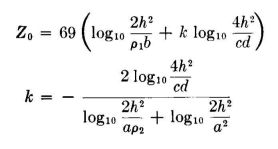
Figures 4.68 to 4.73 show various constructional details that have been used at different broadcast stations. As constructed using wires of radius 0.064 inch, this line is capable of transmitting a peak power of the order of 600 kilowatts, and with larger conductors this rating , can be increased. Its characteristic impedance, of the order of 230 ohms in its usual form, is a very convenient value for broadcasting applications because the coupling networks usually require values of inductance and capacitance readily realizable with available components. When h >> a,
When ρ1 = ρ2,
A set of characteristic values is:
|
||||||||||||||||||||
| Home Radio-frequency Transmission Lines Useful Transmission-line Configurations More than Four Wires Six-wire Unbalanced Line |
|
|||||||||||||||||||


Last Update: 2011-03-19