| Radio Antenna Engineering is a free introductory textbook on radio antennas and their applications. See the editorial for more information.... |

|
Home  Radio-frequency Transmission Lines High-frequency Transmission-line Switching Radio-frequency Transmission Lines High-frequency Transmission-line Switching |
||||||||||||||


|
  |
|||||||||||||
|
High-frequency Transmission-line SwitchingAuthor: Edmund A. Laport
One of the engineering problems associated with high-frequency radio-station design is that of switching various antennas to various feeders in order to obtain the best utilization of equipment. In high-frequency operations it is necessary to change the working frequency during a day over a given circuit and also to use the same transmitters at different times on different circuits. To accomplish this, various switching arrangements are employed. The techniques differ with the particular switching requirements, the type of feeder used, and with the power level of transmission.
Switching devices of many kinds have been developed for this purpose. The use of radio-frequency contactors is the simplest method when suitable designs are available and when one or two transmitters only are
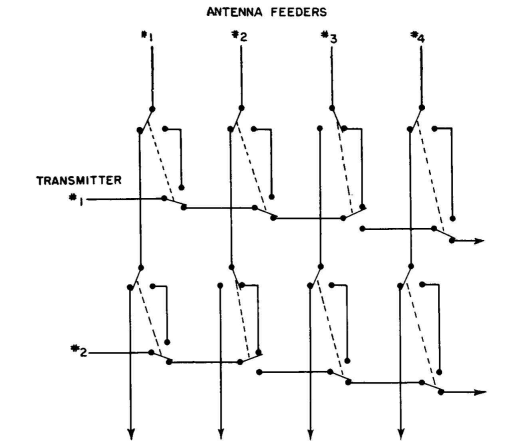
contactors. involved, with a small number of feeders. Double-pole two-position contactors have been used satisfactorily with two-wire balanced feeders at peak powers of 200 kilowatts, as required for 50-kilowatt amplitude-modulated broadcast transmitters at frequencies used for international short-wave broadcasting. Above this power, specially built switching devices are necessary. Figure 4.93 shows an installation of contactors for switching one 50-kilowatt transmitter to any one of eight feeders, using a circuit similar to that of Fig. 4.52. The system uses 600-ohm balanced feeders. Another basic circuit for unlimited flexibility of switching combinations is a form of the crossbar system, as represented schematically in Fig. 4.53. The feeders to the several antennas, with suitable separations to reduce cross talk sufficiently, are distributed in parallel in one plane. The lines from the several transmitters are similarly distributed in another parallel plane, but with their directions normal to the antenna feeders. To connect any antenna feeder to any transmitter feeder, it is necessary only to provide some form of connection between the appropriate feeders at the places where they cross each other. If the feeder conductors are of fixed lengths, this may leave open-circuited stub sections bridging the connections which constitute a point of reflection. If it is not convenient to open the stub sections near these connections to eliminate this undesirable effect, the stub sections can be constructed to have sufficient length to project a quarter wavelength beyond the junction, where they can be short-circuited by contactors or switches. Figure 4.53 shows this principle for one connection between a transmitter and a feeder.
It is possible in the application of the crossbar system to provide an electromechanical device equivalent to two double-pole double-throw switches so that the excess lengths of feeder beyond a junction are open-circuited in the same operation that makes the crossbar connection. A radio-frequency switchboard circuit using this method of eliminating dead ends is shown (for one side of a balanced circuit only) in Fig. 4.54,
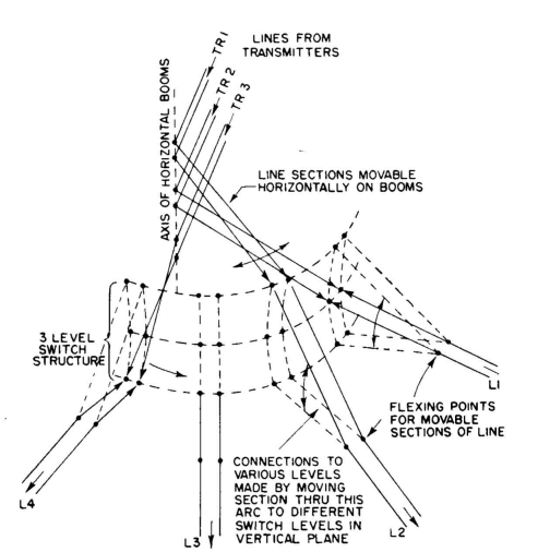
There is a class of large multipole multiposition switch that has come to be known as the "boom" switch. Switches of this type require considerable space because sections of two-wire transmission line of the normal proportions are used for the movable sections. They are usually constructed out of doors for high-power applications. Figure 4.55 shows diagrammatically a two-pole multiposition version, suitable for interconnecting one transmitter to a multiplicity of feeders. Figure 4.56 represents a boom switch, in which are shown three transmitter feed lines leading to a three-level structure (one for each transmitter) in which each transmitter feeder is movable horizontally to a number of pairs of switch points in a horizontal arc.
Each pair of switch points in each level cooperates with an antenna-feeder movable section that connects it with a transmitter feeder as required. The antenna feeders have flexible sections that can move from level to level in a vertical plane. This circuitry gives direct connections between any transmitter feeder and any antenna feeder without dead ends and without any substantial irregularity in the characteristic impedance of the system as a whole. As shown in Fig. 4.56, the following switching combinations can be noticed: Transmitter 1 is connected to antenna feeder 2. Transmitter 2 is connected to antenna feeder 1. Transmitter 3 is connected to antenna feeder 4. Since the transmitter feeders are flexed horizontally and the antenna feeders vertically, it is necessary to make a 90-degree transposition in the flexible part of the transmitter feeder. It enters the switch with its plane vertical and turns 90 degrees to cooperate with the insulated switch points, which are horizontally disposed, where the antenna feeders also connect.
The structure supporting the movable transmitter-feeder section of the switch may be supported on a boom structure, the outer end of which may roll on tracks around its full arc. The design of a structure of this kind is one requiring considerable ingenuity in large-scale electromechanics. It must be operable with ease in high winds and during icing. It must be separately operable by sections while other portions of the switch are energized and in operation, with complete safety to men and equipment. All the principles of the uniform transmission line must be observed. For these reasons they are quite expensive to design and construct.
Boom and drum switches of the type of Fig. 4.55 can be used in combination to obtain complete flexibility of switching a multiplicity of transmitters to a multiplicity of feeders, as shown in Fig. 4.57.
31 They may be fully manual also. The movable members for a manual system can be sections of transmission line which are moved to the points desired. Early systems of the Daventry station of the British Broadcasting Corporation used this method. Other switching needs arise in station design, such as reversing the beam of a dipole array by interchanging radiator and reflector curtains (see Fig. 4.94) or switching the direction of feed and dissipation lines in reversing the directivity of a rhombic antenna. Switching of this sort can be done with a double-pole double-throw switch, though the forms of such switches may be greatly varied by different designers for different particular applications.
|
||||||||||||||
| Home Radio-frequency Transmission Lines High-frequency Transmission-line Switching |
|
|||||||||||||


Last Update: 2011-03-19