| Transistor Basics is a free introductory textbook on transistors and their basic applications. See the editorial for more information.... |

|
Home  The Grounded Base Transistor Vacuum Tubes Compared with Transistors The Grounded Base Transistor Vacuum Tubes Compared with Transistors |
||
| See also: Four-Terminal Networks | ||


|
  |
|
|
Vacuum Tubes Compared with TransistorsAuthor: Leonard Krugman Representation of a vacuum-tube circuit by an equivalent circuit which includes its transconductance, amplification factors, plate resistance, and grid resistance is particularly useful in design applications. This treatment greatly simplifies analysis in those applications of the tube's operating characteristics where a linear approximation is valid. A similar type of linear analysis is applicable to the operation of the transistor. As will be seen shortly, transistor parameters correspond closely to tube parameters. The main factor contributing to differences between tube and transistor characteristics is that the transistor is primarily a current operated device, while a vacuum tube is a voltage operated device. In the transistor, both the input and output currents and voltages are significant. In addition, it is possible to have two or more sets of currents for one set of voltages. This situation is somewhat similar to that existing in a vacuum tube that draws grid current, in which there may be two possible grid voltages for a given set of grid and plate currents. In the transistor, there can only be one set of voltages for a specified pair of input and output currents. This reason governs the choice of current as the independent variable in transistor work as opposed to the choise of voltage in the representation of vacuum-tube characteristics. In vacuum tubes the input grid voltage is plotted against a plate characteristic, because the output voltage is approximately a linear function of the grid voltage. In transistor circuitry, a similar curve can be formed by plotting the collector voltage as a function of collector current for a fixed value of input current. Note again that the transistor input current is selected as the independent variable rather than input voltage. The grounded-cathode vacuum tube is a voltage amplifying device having a high input impedance and a relatively low output impedance. Its equivalent transistor circuit, the grounded emitter transistor, is a current amplifying device with a low input impedance and a relatively high output impedance.
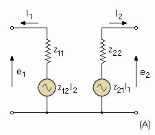
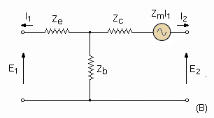
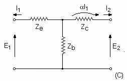
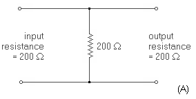
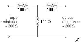
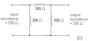
Fig. 3-4. Types of four-terminal equivalent circuits. Several types of equivalent circuits can be used to represent the transistor under small signal conditions. Figure 3-4 represents only three of the many possibilities. The indicated circuits are equivalent in that they all give the same performance for any given set of input and output characteristics. Examples (B) and (C) are particularly well suited to transistor application because the resulting parameters are of significance in transistor physics. In addition, the parameters are readily measured, are usually positive, and are not extremely dependent on the exact operating point chosen. The significance of the impedance parameters is covered later in the chapter. The derivations of these equivalent circuits are based on the relationship between the input and output currents and voltages. For example, assume that for the sealed network of Fig. 3-1 the input and output resistances remain constant with frequency and are each equal to 200 ohms. Then the network may be a shunt resistor equal to 200 ohms (Fig. 3-5A), a "T" pad of three equal 100-ohm resistors (Fig. 3-5B), a "pi" pad of three equal 300-ohm resistors (Fig. 3-5C), or any other combination meeting the required input and output characteristics. The derivations of active networks are admittedly more complicated than this simple example, but the basic principles are exactly the same.
Fig. 3-5. Examples of four-terminal networks.
|
||
| Home The Grounded Base Transistor Vacuum Tubes Compared with Transistors |
|
|
Last Update: 2007-03-23