| Transistor Basics is a free introductory textbook on transistors and their basic applications. See the editorial for more information.... |

|

Home  The Grounded Base Transistor The Grounded Base Transistor  Four-Terminal Analysis of Transistors Four-Terminal Analysis of Transistors  Introduction Introduction |
||


|
||
|
Four-Terminal Analysis of TransistorsAuthor: Leonard Krugman Like the vacuum tube triode, the transistor has useful properties in any of the three possible connections: grounded base, grounded emitter, and grounded collector.
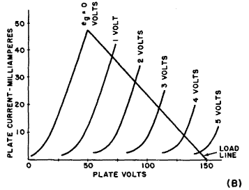
Fig. 3-6. (A) Typical junction-transistor characteristics. (B) Typical vacuum-tube characteristics. Typical characteristics for a junction transistor in grounded base connection are shown in Fig. 3-6 (A). Since the collector current is the independent variable, it is plotted along the abscissa, in apposition to the method used in plotting vacuum tube characteristics. Notice the similarity between the junction transistor characteristics in Fig. 3-6 (A) and those of the typical triode vacuum tube illustrated in Fig. 3-6 (B). Based on this similarity, it is reasonable to assume that the transistor collector voltage, collector current, and emitter current can be compared with the plate current, plate voltage, and grid voltage of a triode vacuum tube. Examining the tube characteristics, it is seen that a signal applied to the grid shifts the plate voltage along the load line. The numerical plate voltage shift caused by a change of one volt in the grid voltage is defined as the amplification factor μ of the tube. In a like manner, applying a signal to the transistor emitter shifts the collector current along the load line. The numerical shift in collector current caused by a change in emitter current of one milliampere is defined as the current amplification factor α of the transistor. The current amplificaton factor of a transistor, then, corresponds to the voltage amplification factor of a vacuum tube. Insofar as input characteristics are concerned, the vacuum tube normally operates with its grid biased in the reverse or high resistance direction, while the transistor operates with the emitter biased in the forward or low resistance direction. In the output circuits, a similar relationship exists. The plate of a vacuum tube is biased in the forward direction, while the transistor collector is biased in the reverse direction. These biasing conditions produce the high input and low output impedances in the vacuum tube circuit, and the low input and high output impedances in the transistor circuit. This re-emphasizes the basic difference between the vacuum tube and the transistor: the vacuum tube is a voltage controlled device, while the transistor is a current controlled device.
|
||
Home  The Grounded Base Transistor The Grounded Base Transistor  Four-Terminal Analysis of Transistors Four-Terminal Analysis of Transistors  Introduction Introduction |
||
Last Update: 2010-11-17


