| Transistor Basics is a free introductory textbook on transistors and their basic applications. See the editorial for more information.... |

|

Home  Grounded Emitter and Grounded Collector Transistors Grounded Emitter and Grounded Collector Transistors  The Grounded Collector Connection The Grounded Collector Connection  Equivalent Operating Circuit Equivalent Operating Circuit |
||||||||||||||


|
||||||||||||||
|
Grounded Collector ConnectionAuthor: Leonard Krugman
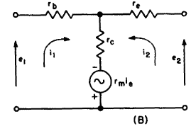
Fig. 4-8. (A) The grounded collector connection. (B) Equivalent active "T" for groundedcollector connection. The general four-terminal parameters can be measured in terms of the internal transistor parameters using the basic measuring circuits of Fig. 3-8. The four-terminal parameter equations for the grounded collector connection are:
These equalities are derived as follows: A.
B.
C.
D.
The numerical values of the four-terminal parameters can now be determined for the typical point-contact transistor. The values are:
The numerical values for the junction transistor are:
Because of the very low values of rb and re compared to the quantities rc and (rc — rm), rn is approximately equal to r21, and r22 is approximately equal to r12.
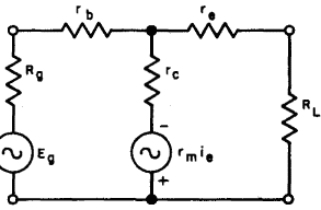
Fig. 4-9. Operating circuit, grounded collector connection Figure 4-9 illustrates the operating circuit for the grounded collector connection. As in the analysis of the grounded emitter circuit, the performance characteristics for this connection can now be determined by straightforward substitution in the general four-terminal circuit equations.
|
||||||||||||||
Home  Grounded Emitter and Grounded Collector Transistors Grounded Emitter and Grounded Collector Transistors  The Grounded Collector Connection The Grounded Collector Connection  Equivalent Operating Circuit Equivalent Operating Circuit |
||||||||||||||
Last Update: 2010-11-17


 when i2 = 0, r11 = rb + rc
 when i2 = 0, r21 = rc
 when i1 = 0, r12 = rc - rm
 when i1 = 0, r22 = re + rc— rm


