| Transistor Basics is a free introductory textbook on transistors and their basic applications. See the editorial for more information.... |

|

Home  Transistor Amplifiers Transistor Amplifiers  Class A Amplifiers Class A Amplifiers  Distortion Distortion |
||


|
||
|
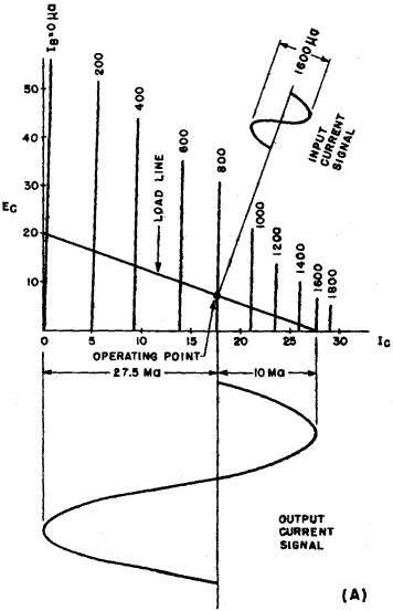
DistortionAuthor: Leonard Krugman Another characteristic of a transistor amplifier that should be mentioned is the harmonic distortion. If the circuit is wired, the distortion can be measured directly, using a suitable wave analyzer or distortion meter. In addition, distortion can be calculated under given operating conditions from the collector characteristics, using the same methods as in vacuum-tube amplifiers.
If the input resistance of the amplifier is high compared to the source impedance, another type of distortion, due to variations in the input circuit, is introduced. In the region of low collector current, the input resistance increases, thus reducing the amplitude of the input signal. In the high region of the collector a-c current cycle, the input resistance decreases, thus increasing the amplitude of the input signal. This type of non-linear distortion is illustrated in Fig. 5-9 (B).
Fig. 5-9. (A) Distortion due to crowding of collector characteristic.(B) Effect of input distortion on output wave. Since the two major types of distortion described above have opposite effects, it will be possible to counteract one with the other by adjusting the value of the signal generator impedance. In troubleshooting multi-stage transistor amplifiers, an output waveform similar to that indicated in Fig. 5-9 (B) would probably indicate a defect in one of the preceding stages. When computing the harmonic distortion of a transistor amplified by conventional vacuum-tube graphical methods, the computed value is generally in the order of 1% less than the measured value. This is caused by the assumption that the signal generator resistance is negligible, a condition seldom realized in low input resistance transistor circuits. The source resistance in vacuum-tube amplifiers does not affect the determination of the harmonic distortion, since the grid current is zero. However, the equivalent parameter in transistor amplifiers, the base-emitter voltage, is not zero. The effect of the source may be taken into account by considering it as part of the base resistance. However, in most applications, it is more than satisfactory to simply add 1% to the calculated value of percentage distortion.
|
||
Home  Transistor Amplifiers Transistor Amplifiers  Class A Amplifiers Class A Amplifiers  Distortion Distortion |
||
Last Update: 2010-11-17


