| Transistor Basics is a free introductory textbook on transistors and their basic applications. See the editorial for more information.... |

|

Home  Transistor Amplifiers Transistor Amplifiers  Transistor Gain Controls Transistor Gain Controls |
|||


|
|||
|
Transistor Gain ControlsAuthor: Leonard Krugman
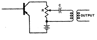
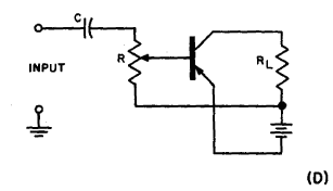
Despite the relatively low gain of transistor amplifiers, a gain control is frequently necessary to compensate for changes in the input sig- nal, the ambient noise level, and other variations. The design of volume controls for transistor circuits is not a difficult problem if the fact that transistors are current operated devices is kept in mind. Figure 5-15 (A) illustrates one possible form of output gain control in a R-C coupled stage. In this circuit, the output potentiometer sets both the collector d-c operating point and the level of the output signal. The coupling capacitor blocks d-c current from flowing into the load. The value of this capacitor must be large enough to pass the lowest frequency to be amplified. If the output load is a transformer, this same form of gain control is not satisfactory, since, as illustrated in Fig. 5-15 (B), the load impedance varies with the potentiometer setting. If the coupling capacitor is omitted, circuit operation is poorer because the volume control setting changes the d-c operating point. Figure 5-15 (C) illustrates a satisfactory form of input volume control in a transformer coupled stage. The resistance of the potentiometer should be at least ten times the value of the secondary-winding impedance to make its loading effect negligible. The arrangement illustrated in Fig. 5-15 (D), however, is not satisfactory, because the base bias varies with changes in the volume control setting. In multistage operation, the gain control may be located in the input or output circuit of any stage. It is usually desirable to place the control in the first stage if the signal amplitude is likely to vary appreciably. This arrangement helps to prevent the system from overloading on large signals.
|
|||
Home  Transistor Amplifiers Transistor Amplifiers  Transistor Gain Controls Transistor Gain Controls |
|||
Last Update: 2007-03-21


