| Transistor Basics is a free introductory textbook on transistors and their basic applications. See the editorial for more information.... |

|
Home  Transistor Amplifiers Cascade Operation Cascade Design Transistor Amplifiers Cascade Operation Cascade Design |
||


|
  |
|
|
Cascade DesignAuthor: Leonard Krugman
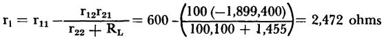
The input resistance of the last stage (equation 3-13) is expressed as:
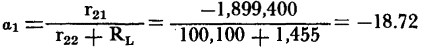
and the current gain (equation 3-8) is:
Since rm is close to the value of rc, the intermediate stage is restricted to the grounded emitter connection. For this stage:
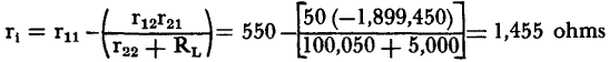
Since the input resistance of the last stage is the output resistance of the intermediate stage, RL = 5,000 ohms. The input resistance of the intermediate stage is
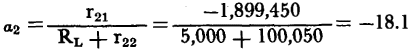
and the current gain is:
Since a low value of Rg is specified, the first stage must use either the grounded emitter or the grounded base connection. The load of the first stage equals the input resistance of the intermediate stage and is a low value. Therefore, the best choice for the first stage is the grounded emitter connection. Since Rg was specified as being adjustable, its value will be made equal to the input resistance,
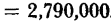
The current gain is: The overall current α = α1α2α3 = (-18.75) (-18.1) (19.99) = 6,780 The operating gain (equation 5-1) is
The resulting cascade circuit is shown in Fig. 5-17. This circuit does not include biasing arrangements, coupling networks and feedback loops. The values of the elements necessary for introducing these requirements may be computed by the methods in preceding paragraphs. The cascade system may be changed considerably by the addition of external resistance arms to the circuits. These have the effect of increasing the effective values of the transistor parameters. For example, consider the effect of adding a stabilizing resistor RE = 50 ohms in series with the emitter arm of the input stage. The effective resistance of the emitter is now re -f- RE = 50 -f 50 = 100 ohms, and the general four-terminal parameters are now:
The input resistance
and the current gain
The overall current gain and the operating gain
Thus, a simple change reduces the overall system gain by a factor of one-half. It is evident that even after the basic stage connections are fixed, a considerable variation in the cascade performance and resistance terminal characteristics can be attained by changes in the effective value of the transistor parameters.
|
||
| Home Transistor Amplifiers Cascade Operation Cascade Design |
|
|


 gain of the cascaded system


Last Update: 2010-11-17