| Transistor Basics is a free introductory textbook on transistors and their basic applications. See the editorial for more information.... |

|

Home  Transistor Oscillators Transistor Oscillators  Negative-Resistance Oscillators Negative-Resistance Oscillators  General Types General Types |
||


|
||
|
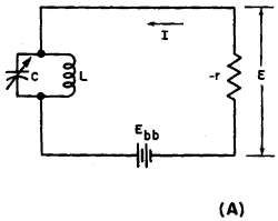
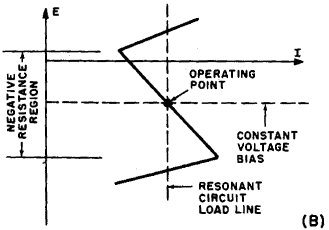
General TypesAuthor: Leonard Krugman Negative-resistance oscillators may be divided into two general classes: voltage controlled; and current controlled. The voltage-controlled oscillator is characterized by a high resistance load, and a low resistance power supply (constant voltage). The fundamental schematic of a typical oscillator of this type is illustrated in Fig. 6-7 (A).
Fig. 6-7. (A) Voltage controlled negative resistance equivalent circuit. (B) Idealized current-voltage characteristic. This oscillator is composed of three major parts: the resonant L-C circuit, the negative resistance of the oscillator, and the d-c supply voltage Ebb.
Fig. 6-8. (A) Current-controlled negative resistance equivalent circuit, (B) Idealized current-voltage characteristic. The current-controlled type is shown in Fig. 6-8 (A). This oscillator is characterized by a low a-c load and a high d-c power source (constant current). Figure 6-8 (B) represents the idealized current-voltage characteristics for this negative-resistance oscillator. As in the voltage-controlled type, the negative-resistance region is limited to a section of the operating range, and the bias is established somewhere in the middle of this negative-resistance region using a constant current source. The last condition to be satisfied for sustained oscillation is that the a-c load of the resonant circuit must be less than the absolute value of negative resistance of the oscillator at the operating point. The series L-C circuit, the resonant impedance of which is close to zero, is the ideal load for this application.
|
||
Home  Transistor Oscillators Transistor Oscillators  Negative-Resistance Oscillators Negative-Resistance Oscillators  General Types General Types |
||
Last Update: 2010-11-17


