| Transistor Basics is a free introductory textbook on transistors and their basic applications. See the editorial for more information.... |

|

Home  Transistor Oscillators Transistor Oscillators  Negative-Resistance Oscillators Negative-Resistance Oscillators  Sine-wave Oscillators Sine-wave Oscillators |
||


|
||
|
Sine-wave OscillatorsAuthor: Leonard Krugman
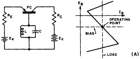
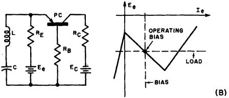
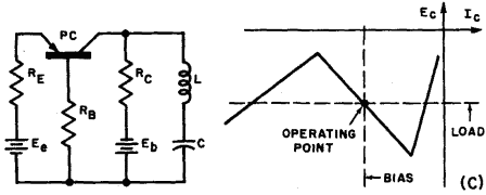
Fig. 6-9. (A) Base-controlled negative resistance oscillator and idealized characteristic. (B) Emitter-controlled negative resistance oscillator and idealized characteristic. (C) Collector-controlled negative resistance oscillator and idealized characteristic. Figure 6-9 (B) represents the basic emitter controlled negative resistance oscillator and its idealized current-voltage characteristics. Fig. 6-9 (C) is the basic collector controlled type. The fundamental operation of both is essentially the same. Oscillation occurs at the series resonant frequency of the L-C combination because at this point the effective resistance in either the emitter or collector arm is at minimum. The base resistance must be large enough to furnish positive feedback in order to sustain oscillation. The base resistance rb is generally large enough to cause instability when either the emitter or collector is shorted to ground, on the basis of equation 6-1. In practical circuits, however, rb alone is rarely enough for dependable operation. An external resistor RB equal to at least 2,000 ohms is generally added.
|
||
Home  Transistor Oscillators Transistor Oscillators  Negative-Resistance Oscillators Negative-Resistance Oscillators  Sine-wave Oscillators Sine-wave Oscillators |
||
Last Update: 2010-11-17


