| Wireles Networking is a practical guide to planning and building low-cost telecommunications infrastructure. See the editorial for more information.... |

|
Home  Antennas and Transmission Lines Practical Antenna Designs Collinear Omni Antenna Antennas and Transmission Lines Practical Antenna Designs Collinear Omni Antenna |
|||||||||||||||||||||||||||||||||||||||


|
  |
||||||||||||||||||||||||||||||||||||||
|
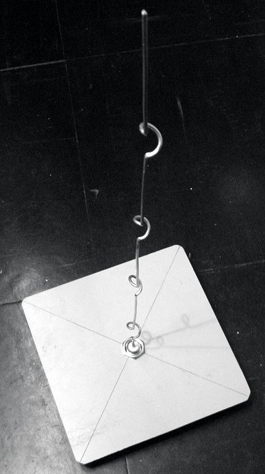
Collinear Omni AntennaThis antenna is very simple to build, requiring just a piece of wire, an N socket and a square metallic plate. It can be used for indoor or outdoor Point-to-MultiPoint short distance coverage. The plate has a hole drilled in the middle to accommodate an N type chassis socket that is screwed into place. The wire is soldered to the center pin of the N socket and has coils to separate the active phased elements. Two versions of the antenna are possible: one with two phased elements and two coils and another with four phased elements and four coils. For the short antenna the gain will be around 5dBi, while the long one with four elements will have 7 to 9 dBi of gain. We are going to describe how to build the long antenna only.
Parts list
Tools required
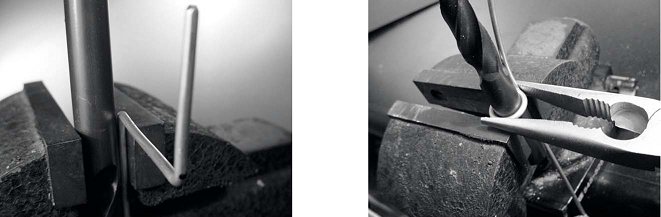
Construction1. Straighten the wire using the vice.
2. With a marker, draw a line at 2.5 cm starting from one end of the wire. On this line, bend the wire at 90 degrees with the help of the vice and of the hammer.
3. Draw another line at a distance of 3.6 cm from the bend. Using the vice and the hammer, bend once again the wire over this second line at 90 degrees, in the opposite direction to the first bend but in the same plane. The wire should look like a 'Z'.
4. We will now twist the 'Z'portion of the wire to make a coil with a diameter of 1 cm. To do this, we will use the pipe or the drill bit and curve the wire around it, with the help of the vice and of the pliers.
The coil will look like this:
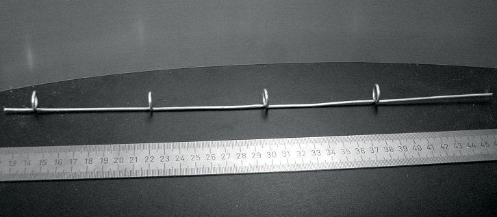
5. You should make a second coil at a distance of 7.8 cm from the first one. Both coils should have the same turning direction and should be placed on the same side of the wire. Make a third and a fourth coil following the same procedure, at the same distance of 7.8 cm one from each other. Trim the last phased element at a distance of 8.0 cm from the fourth coil.
If the coils have been made correctly, it should now be possible to insert a pipe through all the coils as shown.
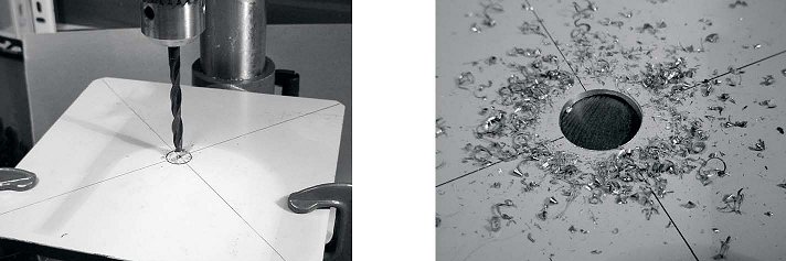
6. With a marker and a ruler, draw the diagonals on the metallic plate, finding its center. With a small diameter drill bit, make a pilot hole at the center of the plate. Increase the diameter of the hole using bits with an increasing diameter.
The hole should fit the N connector exactly. Use a file if needed.
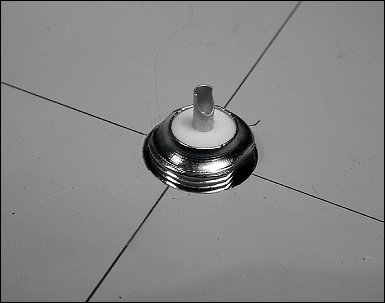
7. To have an antenna impedance of 50 Ohms, it is important that the visible surface of the internal insulator of the connector (the white area around the central pin) is at the same level as the surface of the plate. For this reason, cut 0.5 cm of copper pipe with an external diameter of 2 cm, and place it between the connector and the plate.
8. Screw the nut to the connector to fixit firmly on the plate using the spanner.
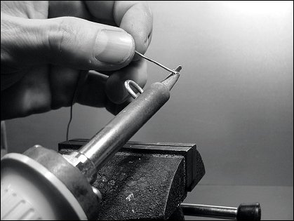
9. Smooth with the file the side of the wire which is 2.5 cm long, from the first coil. Tin the wire for around 0.5 cm at the smoothed end helping yourself with the vice.
10. With the soldering iron, tin the central pin of the connector. Keeping the wire vertical with the pliers, solder its tinned side in the hole of the central pin. The first coil should be at 3.0 cm from the plate.
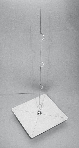
11. We are now going to stretch the coils extending the total vertical length of the wire. Using the use the vice and the pliers, you should pull the cable so that the final length of the coil is of 2.0 cm.
12. Repeat the same procedure for the other three coils, stretching their length to 2.0 cm.
13. At the end the antenna should measure 42.5 cm from the plate to the top.
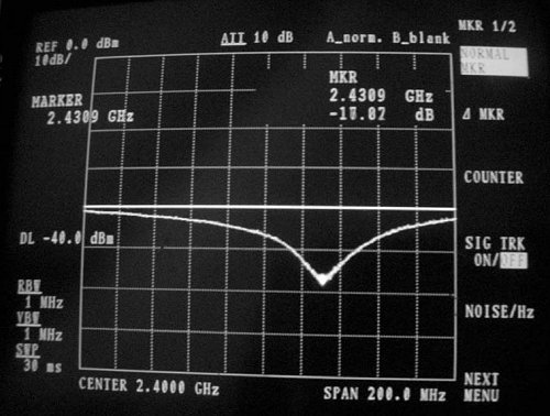
14. If you have a Spectrum Analyzer with Tracking Generator and a Directional Coupler, you can check the curve of the reflected power of the antenna. The picture below shows the display of the Spectrum Analyzer.
If you intend to use this antenna outside, you will need to weatherproof it. The simplest method is to enclose the whole thing in a large piece of PVC pipe closed with caps. Cut a hole at the bottom for the transmission line, and seal the antenna shut with silicone or PVC glue.
|
|||||||||||||||||||||||||||||||||||||||
| Home Antennas and Transmission Lines Practical Antenna Designs Collinear Omni Antenna |
|
||||||||||||||||||||||||||||||||||||||


Last Update: 2007-01-14