| Wireles Networking is a practical guide to planning and building low-cost telecommunications infrastructure. See the editorial for more information.... |

|
Home  Antennas and Transmission Lines Practical Antenna Designs Cantenna Antennas and Transmission Lines Practical Antenna Designs Cantenna |
|||||||||||||||||||||||
| See also: Horn Antenna, Cantenna as Dish Feed | |||||||||||||||||||||||


|
  |
||||||||||||||||||||||
|
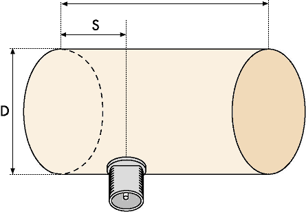
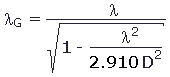
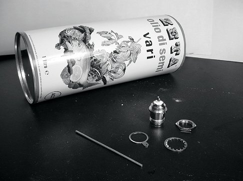
CantennaThis antenna, sometimes called a Cantenna, uses a tin can as a waveguide and a short wire soldered on an N connector as a probe for coaxial-cable-to waveguide transition. It can be easily built at just the price of the connector, recycling a food, juice, or other tin can. It is a directional antenna, useful for short to medium distance point-to-point links. It may be also used as a feeder for a parabolic dish or grid. Not all cans are good for building an antenna because there are dimensional constraints:
L
The gain for this antenna will be in the order of 10 to 14 dBi, with a beam-width of around 60 degrees.
Parts list
Tools required
Construction1. With the can opener, remove carefully the upper part of the can.
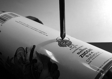
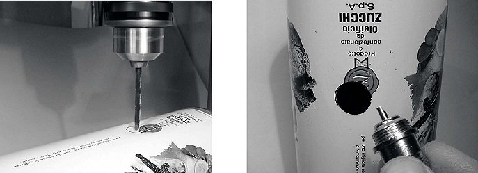
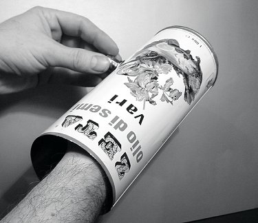
The circular disk has a very sharp edge. Be careful in handling it! Empty the can and wash it with soap. If the can contained pineapple, cookies, or some other tasty treat, have a friend serve the food. 2. With the ruler, measure 6.2 cm from the bottom of the can and draw a point. Be careful to measure from the inner side of the bottom. Use a punch (or a small drill bit or a Phillips screwdriver) and a hammer to mark the point. This makes it easier to precisely drill the hole. Be careful not to change the shape of the can doing this by inserting a small block of wood or other object in the can before tapping it.
3. With a small diameter drill bit, make a hole at the center of the plate. Increase the diameter of the hole using bits with an increasing diameter. The hole should fit exactly the N connector. Use the file to smooth the border of the hole and to remove the painting around it in order to ensure a better electrical contact with the connector.
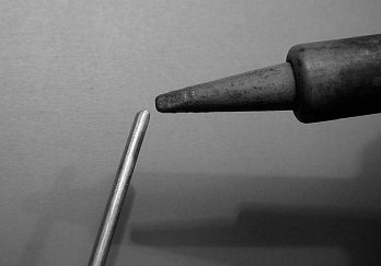
4. Smooth with the file one end of the wire. Tin the wire for around 0.5 cm at the same end helping yourself with the vice.
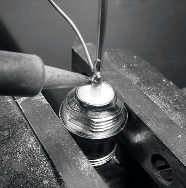
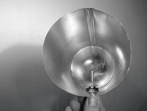
5. With the soldering iron, tin the central pin of the connector. Keeping the wire vertical with the pliers, solder its tinned side in the hole of the central pin.
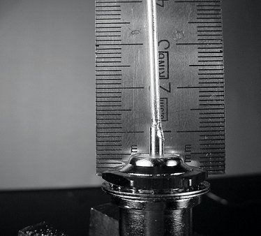
6. Insert a washer and gently screw the nut onto the connector. Trim the wire at 3.05 cm measured from the bottom part of the nut.
7. Unscrew the nut from the connector, leaving the washer in place. Insert the connector into the hole of the can. Screw the nut on the connector from inside the can.
8. Use the pliers or the monkey wrench to screw firmly the nut on the connector. You are done!
As with the other antenna designs, you should make a weatherproof enclosure for the antenna if you wish to use it outdoors. PVC works well for the can antenna. Insert the entire can in a large PVC tube, and seal the ends with caps and glue. You will need to drill a hole in the side of the tube to accommodate the N connector on the side of the can.
|
|||||||||||||||||||||||
| Home Antennas and Transmission Lines Practical Antenna Designs Cantenna |
|
||||||||||||||||||||||


Last Update: 2010-12-02