| Basic Radio is a free introductory textbook on electronics based on tubes. See the editorial for more information.... |

|
Home  Transmission of Signals Long-Lines Non-Resonant Transmission Lines Transmission of Signals Long-Lines Non-Resonant Transmission Lines |
||||||||||||||


|
  |
|||||||||||||
|
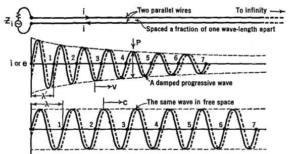
Non-Resonant Transmission LinesAuthor: J.B. Hoag At the top of Fig. 35 C there are two parallel wires extending from the generator at the input end at the left to infinity at the right.
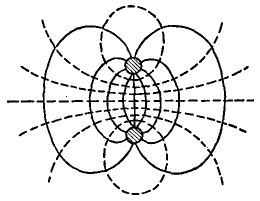
The separation between the wires is only a fraction of one wave-length. At a given moment, when the top of the generator is positive and the bottom is negative, the electric and magnetic fields at the left end of the wires will appear as in Fig. 35 D, the dotted lines representing the magnetic field.
As time goes on, these fields progress down the wires. Since they are set up by the moving charges (currents) in the wires, they are constrained to follow the wires, be they straight or curved. Thus a long-line may be thought of as, and in truth is, a wave-guide.
This follows from the simple fact that the wires are hooked onto the opposite terminals of the generator. Because the magnetic field of one current is always reversed from that set up by the other current, a negligible amount of radiation takes place. This is but another way of saying that the wires, by preventing outward radiation, serve as wave-guides. The outward progression of energy from the generator or input terminal of the line may be represented as a sinusoidal wave, as in the central part of Fig. 35 C. The solid wave represents conditions at a given moment, a flashlight picture or instantaneous view, while the dotted wave shows its position a short time later. If we could observe the impulse as it moved down the line past a fixed point, say P in the figure, we would find that the current had a maximum value in one direction, decreased to zero, reversed its direction and increased to a maximum, then dropped to zero, repeating a complete cycle once for each period of the generator. The current in the other wire would do the same, but would always be directed oppositely to the first one. As the wave progresses along the line, some energy is lost in the form of radiation, some in heating the wires, some in leaking through the air or other insulation between the wires. This loss of energy takes place " exponentially " or " logarithmically " along the line, and is represented in Fig. 35 C by the gradual decrease in the amplitude of the wave from left to right. Thus, on a long-line we have a damped, progressive wave. The velocity with which the wave progresses down the line is less than that in free space; that is, it is less than 3 · 1010 cms. per sec. The numerical value of the velocity can be computed from the geometry of the line and the nature of the conductors and dielectrics between the conductors. The equation for the velocity is
where L and C are the distributed inductance and capacitance of a one-centimeter length of the double line. Formulas have been derived for L and C in terms of the size of the wires, their magnetic properties, their spacing, and the kind of insulation between them. Inasmuch as the frequency of the generator is a fixed quantity, whereas the velocity along the wires is less than that in free space, the wave-length λ' along the wires is less than that in free space. Since the frequency of the oscillator is constant, whether it sends its energy into the transmission line or out into free space, we may write
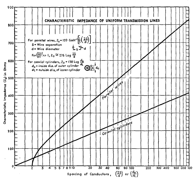
For a long-line of the parallel wire type which we are considering here, made of copper wires spaced from 2 to 6 inches apart, λ' is approximately 0.975λ or, in other words, the wave travels down the wire at about 97.5 per cent the velocity of light. Although the amplitudes decrease as the wave goes out along the line, the ratio of the voltage across the line to the current at any one point in the line is the same as that at another point. This ratio is called the characteristic impedance, Zc, of the line. Just as the velocity of propagation is determined by the geometry of the line and the medium between the conductors, so also we find that Zc can be computed in terms of the " line constants." The equation is
Values of this important quantity are shown in Fig. 35 E.
In this figure it will be noticed that it is possible to design a line by choosing the sizes of the conductors and their spacing so as to obtain a desired characteristic impedance anywhere from a comparatively small value up to several hundred ohms. In practice, transmission lines are not infinitely long. However, if a resistance numerically equal to the characteristic line impedance is connected across the output end of a transmission line of finite length, the line will act at its input end exactly like one of infinite length. A wave which has traveled the length of the line will be completely absorbed in the terminating impedance. No reflection will occur at the output end. The line is said to be non-resonant. The length of a line can be expressed in feet, meters, or other units. Because of the vital importance of the relative length of the line and the length of the radio wave, it is often given in terms of the number of wave-lengths which, laid end to end, would reach from the input to the output terminals. A little care is needed here, because the wavelength of the waves along the line (λ') is somewhat shorter than that of the waves radiated outwards into free space (λ) as shown in Fig. 35 C. If l stands for the actual length of the line in feet, and f for the frequency of the generator in MHz, then the number n of free-space waves (each of length λ) which could be used end to end to measure l is given by n = lf/984. In other words, the physical length of the line is l = 984/f. A line 984 feet long would be 10 wave-lengths long if used with an oscillator whose frequency was 107 Hz (λ = 30 m.) and it would be 100 wave-lengths long for a frequency of 108 (λ = 3m.). Because the wave-length along the line is not that in free space, but somewhat less, the " electrical " length is sometimes used.
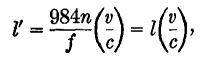
Referring to Fig. 35 F, we see in the lower part an imaginary line of such length that the same number (n = 4) of shortened (λ') waves will fit along it as the number of free-space waves (λ) fit along the actual line l. The electrical length of a line, in feet, is given by
where f is the frequency of the generator in MHz, v is the velocity of the waves along the wires, and c is the velocity in free space. The energy lost along a line can be expressed in decibels per unit length (mile, meter, or free-space wave-length). The values given here will be in db. per wave-length. For a transmission line we wish to lose as little energy as possible, whereas with an antenna the radiation " loss " must be as great as we can make it. The following losses are for transmission lines: non-resonant parallel wires, about 0.14; rubber insulated twisted-pair or coaxial, about 1.00; dry lamp-cord, 1.4; dry air-insulated coaxial, very small. Losses are directly proportional to the length of the line. Thus a dry lamp-cord 3 wave-lengths long will have a loss of 3 · 1.4 = 4.2 db.
|
||||||||||||||
| Home Transmission of Signals Long-Lines Non-Resonant Transmission Lines |
|
|||||||||||||


Last Update: 2010-11-27