| Electronic Transformers and Circuits is a free introductory textbook on transformers and related circuits. See the editorial for more information.... |

|

Home  Amplifier Circuits Amplifier Circuits  Modulation Transformers Modulation Transformers |
||||||||||||||||


|
||||||||||||||||
Modulation Transformers
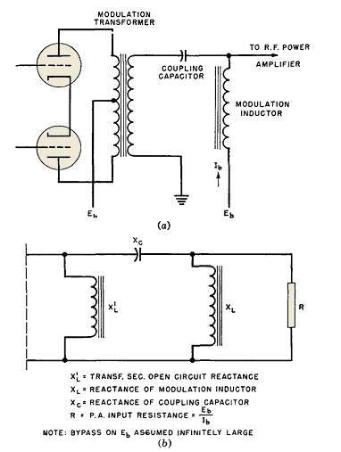
For low modulation frequencies, this method may be illustrated by means of the circuit diagram of Fig. 145(a). The modulator usually is a class B amplifier. Output transformer OCL, coupling capacitor, and modulation reactor combine to form a pi-section high-pass filter, Fig. 145(b). The elements are proportioned for characteristic impedance equal to the equivalent plate input resistance EB/IB of the modulated power amplifier.
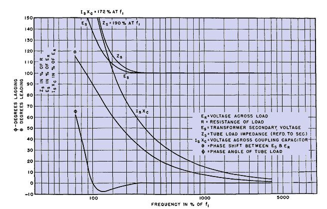
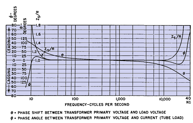
Formerly these components were made as large as was considered practical. Transformer secondary and reactor reactances were each 3 to 4 times the power amplifier plate input resistance, and the coupling capacitor reactance was a fraction of this resistance, at the lowest modulation frequency. Advantages of the pi-filter are a reduction of the two inductive reactances to 1.41 times the terminating load resistance, and increase in capacitive reactance to the same value, at a low frequency f1, which is 1.41 times cut-off frequency of the filter. Down to f1 the filter maintains a tube load of almost 100 per cent power factor, although the ohmic value rises to 190 per cent of the terminating load resistance at f1. The voltage required for constant output rises to 138 per cent of normal. Partly compensating for this defect is the tendency of class B amplifier tubes to deliver higher voltages with higher tube load impedances. Thus, in a certain radio transmitter, the type 805 modulator tubes deliver 1,035 peak volts per side into a normal tube load of 1,860 ohms. At 30 cycles, the lowest audio frequency, the load impedance rises to 3,600 ohms, and the voltage required for full output is 1,440 volts. Plotting a 3,600-ohm load line on the tube curves shows that 1,275 volts will be delivered at 30 cycles, which is 1 db down from normal. To obtain the same frequency response with the older "brute force" method, at least twice the values of transformer and reactor inductance and much more coupling capacitance would have been necessary. The voltage across the capacitor increases as the capacitance decreases, but surge voltages often exist across the coupling capacitor in service. The voltage rating was formerly determined more by these surges than by normal voltage. With the pi-filter method, the normal voltage at low frequencies cannot be greatly exceeded in service, owing to the limitation in voltage output of the tubes. Hence, the reduction in coupling capacitance is a real one and is offset very little by increases in voltage rating.
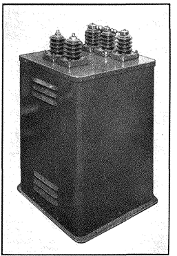
These points are made clearer by reference to Fig. 146. Phase shift between transformer and load voltages is 90° at f1. At cut-off (= 70 per cent of f1) the tube voltage for constant output is 224 per cent of the load voltage. A tube would not deliver so much voltage with this type of load, especially when the power factor is so low. The corresponding capacitor voltage at cut-off frequency is 284 per cent of ER; it would not be delivered either, for the same reason. The useful frequency range is higher than f1. Another advantage of the pi-filter over the older method is the high power factor load down to frequency f1. The maximum tube load phase angle above f1 is 8°, and at frequencies above 3f1 the phase angle is zero. At 3f1 the tube load impedance is equal to R. Hence the tube works into a unity power-factor load of constant value at frequencies above 3f1. For the same size of inductive components, the "brute force" system would have been very much poorer. If these elements had been made twice as large in order to give the same frequency response at 30 cycles, the load phase angle at 30 cycles would be 35° and the load impedance 80 per cent of R. Hence the possibilities of low-frequency distortion and low efficiency are reduced by the pi-filter method. In very high fidelity modulators the lowest frequency is 2 to 3 times f1 to reduce phase shift in connection with the inverse feedback. The pi-filter just discussed conforms with the usual high-pass filter in regard to values of L and C. These elements can be proportioned on another basis such that the ohmic values of all the reactive elements are made equal to the load resistance at frequency f1. These values are those of a 90° artificial line at frequency f1. They give a unity power-factor tube load equal to the modulated power amplifier plate input resistance at frequency f1 and thus represent 41 per cent increase in capacitor and 41 per cent reduction in transformer and reactor size. The disadvantages of the artificial line are that the tube load impedance drops to a minimum of 74 per cent R at the frequency 1.5f1, the maximum tube load phase angle is 16°, and it persists up to frequencies much higher than 3f1, which was the frequency where the response of the pi-filter became virtually perfect. This appreciable phase angle spread over a portion of the audio frequency range, together with the lower load impedance, causes distortion. The artificial line basis of design is used where larger amounts of distortion are not objectionable, or in fixed-frequency modulators. No matter what method of design is used, it is important that the modulator be loaded properly. If the power amplifier input should be interrupted while the modulator is fully excited, the voltages on the various elements are likely to rise to dangerous values, because the load impedance becomes high and causes indefinitely high voltages in the positive eB direction. The transformer and reactor in high-voltage modulators are equipped with spark gaps like those in Fig. 147 to prevent insulation breakdown due to accidental removal of load.
The pi-filter or artificial line method of design can be applied also at the higher modulation frequencies.
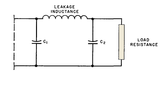
Figure 148 shows how the usual properties of winding capacitance and leakage inductance are arranged to give a low-pass filter circuit. Preferably the internal capacitance and inductance should be so low that external L and C can be added to the transformer terminals to produce the required proportions at the highest modulator frequency.(1)
Figure 149 shows how both high-and low-pass pi-filter performance can be combined in a modulator to obtain wide-range high-fidelity performance. Although these methods apply chiefly to modulation transformers, they may be used in the design of loaded interstage transformers.
In high power modulation transformers, it is necessary to make the core larger in order to reduce the number of turns and obtain good high-frequency response. But, as the core becomes larger, so do the leakage inductance and winding capacitance. The core must grow very large to overcome this difficulty, and high power audio transformers are much larger than commercial power transformers of the same rating. One advantage of grain-oriented steel is that it permits this process to be reversed. High induction at low frequencies means a smaller core area, smaller mean turn, and better high-frequency performance, or, for the same high-frequency performance, more turns and a still smaller transformer. Weight savings of 60 to 75 per cent have been made in this way. Advantages of the pi-filter and artificial line methods are realized in transformers for 30 to 10,000 cycles; some advantage can be gained in the 100- to 5,000-cycle range, but not below 100 watts. Below this size, or for a narrower frequency range, the transformer becomes so small that combination with the modulation reactor into one unit is feasible and economical. The secondary current wave shape is like the first wave of Table I (p. 16). In such a transformer the core gap must be large enough to prevent saturation by the power amplifier plate current.
|
||||||||||||||||
Home  Amplifier Circuits Amplifier Circuits  Modulation Transformers Modulation Transformers |
||||||||||||||||
Last Update: 2011-02-17


