| Electronic Transformers and Circuits is a free introductory textbook on transformers and related circuits. See the editorial for more information.... |

|

Home  Amplifier Circuits Amplifier Circuits  Driver Transformers Driver Transformers |
||||||


|
||||||
Driver Transformers
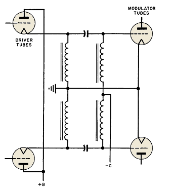
These conditions require transformers of exceptionally large size. For low (1 to 2 per cent) overall harmonic distortion, driver transformer design becomes impractical, and it is advantageous to dispense with driver transformers entirely. This is accomplished by the cathode follower circuit (Fig. 150), which for a push-pull amplifier takes the form of a symmetrical pi-filter.
The two input chokes connect the driver tube cathodes to ground and carry their plate current. Coupling capacitors connect these chokes to the modulator tube grid chokes, which carry modulator grid current. Sizes of chokes and coupling capacitors are chosen to give approximately constant impedance from the lowest modulation frequency up to the higher harmonics of the highest frequency, and choke capacitance is reduced to preclude pronounced resonance effects throughout the frequency range.
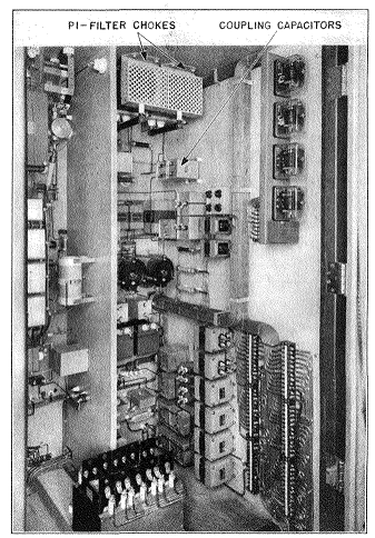
In Fig. 151, the filter components are mounted in the exciter cubicle; a transformer for this purpose would be too large to locate internally. The cathode follower circuit is advantageous in another way. Leakage inductance in a driver transformer causes high-frequency phase shift between driver and grid voltage, which does not exist in the coupling capacitor scheme. Since inverse feedback is often applied to audio amplifiers to reduce distortion, the absence of phase shift is a great advantage. The low frequency at which phase shift appears must be kept below the audio band, but this can be done without excessively large components.
|
||||||
Home  Amplifier Circuits Amplifier Circuits  Driver Transformers Driver Transformers |
||||||
Last Update: 2011-01-24


