| Electronic Transformers and Circuits is a free introductory textbook on transformers and related circuits. See the editorial for more information.... |

|

Home  Amplifier Circuits Amplifier Circuits  Transformer-Coupled Oscillators Transformer-Coupled Oscillators |
||||


|
||||
Transformer-Coupled Oscillators
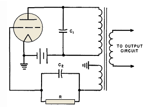
These have circuits similar to that of Fig. 152.
Transformer OCL and capacitor C1 form a tank circuit, to which are coupled sufficient turns to drive the grid in the lower left-hand winding. The output circuit is coupled by a separate winding. For good wave shape in such an oscillator, triodes and class B operation are preferable. The ratio of turns between anode and grid circuits is determined by the voltage required for class B operation of the tube as if it were driven by a separate amplifier stage. Single tubes may be used, because the tank circuit maintains sinusoidal wave shape over the half-cycle during which the tube is not operating. Grid bias is obtained from the RC2 circuit connected to the grid.
Class C oscillators are less desirable for very low harmonic requirements, because of the difficulty of designing tank circuits with sufficiently high Q. Where large harmonic values can be tolerated, the transformer can be designed for low Q, but the wave form becomes non-sinusoidal. Transformer grid circuit turns are large, approximately the same as plate turns, and the grid voltage would be high if grid current did not limit the positive voltage swing. During the half-cycle when the tube is operating, the voltage wave has a roughly rectangular shape, and during the rest of the cycle it peaks sharply to a high amplitude in the opposite direction. Core losses are difficult to predict because loss data are not normally available for such wave forms. Consequently, designs of this type are usually cut-and-try. The frequency of oscillation varies with changes in load; hence low Q class C oscillators are to be avoided if good frequency stability is required.
|
||||
Home  Amplifier Circuits Amplifier Circuits  Transformer-Coupled Oscillators Transformer-Coupled Oscillators |
||||
Last Update: 2011-01-24


