| Electronic Transformers and Circuits is a free introductory textbook on transformers and related circuits. See the editorial for more information.... |

|

Home  Amplifier Circuits Amplifier Circuits  Hybrid Coils Hybrid Coils |
||||||||||||||||||


|
||||||||||||||||||
Hybrid Coils
Hybrid coils are used to isolate an unwanted signal from certain parts of a circuit, and allow the signal to be used in other parts of the circuit.
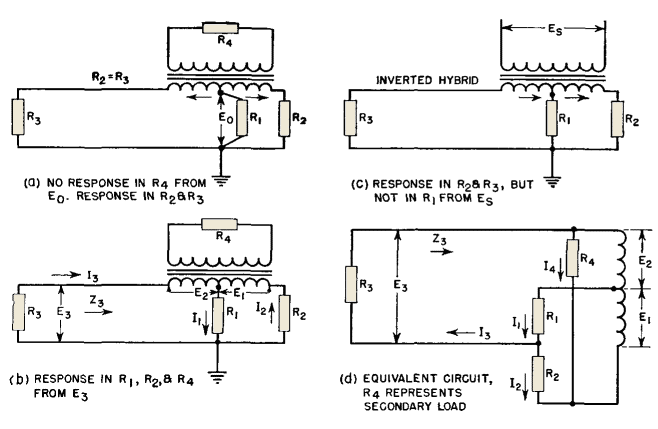
In the hybrid coil shown in Fig. 156 (a) the lower windings or primary sections are balanced with respect to each other, and the two resistors R2 and R3 are equal. Voltage E0 applied between the primary center tap and ground causes equal currents to flow in opposite directions through the two halves of the primary winding, and therefore produces zero voltage in the secondary winding. By this means, signal E0 arrives at resistors R2 and R3 undiminished, but there is no voltage in R4 connected across the secondary coil. Figure 156(b) shows what happens in this circuit if the voltage is applied across R3 instead of across R1. In this case, the voltage E3 appears across resistors R1, R2, and R4, that is, in all parts of the circuit.
It has been assumed that R2 and R3 are equal and that the two primary half-windings are of equal number of turns. This is not necessarily true, for, if the resistance of R2 is twice that of R3, the number of turns connected to R2 should be twice those connected to R3. However, it is important that, through the range of frequency in which the hybrid coil is desired to function, the balance between the two halves be maintained closely. The most exact balance is achieved for R2 = R3 by winding the two halves simultaneously with two different wires. This method gives good isolation of the undesired signal. Other methods introduce some ratio error which reduces the isolation. For the same reason, it is necessary to balance the circuit with regard to capacitance and leakage inductance. That is, if a capacitance exists across R3, such as line capacitance for example, an additional equivalent amount should be added across R2 in order to achieve the balance desired. Likewise, any inductive apparatus, adding either series or parallel inductance in one circuit, should be compensated for by inductance of like character in the other circuit. Adding series inductance, for example, in series with R3 will not compensate for shunt inductance across R2, or vice versa, as the two have opposite effects with regard to frequency and therefore balance is attained only at one frequency. Assume a perfect transformer having no exciting current and no leakage inductance between the two halves, and a transformer with equal turns in the two halves of the primary winding. Assume currents in the directions shown in Fig. 156 (d). Then
On the assumption of equal turns in the two half-windings, E1 = E2. If the magnetizing current is assumed to be zero, the ampere-turns and hence the volt-amperes in the two primary halves are equal. The secondary load can be considered as reflected into the primary winding as resistor R4.
If equations 88 to 92 are combined, an expression for Z3 can be found:
If the secondary circuit is open, R4 = ∞, and equation 93 becomes
|
||||||||||||||||||
Home  Amplifier Circuits Amplifier Circuits  Hybrid Coils Hybrid Coils |
||||||||||||||||||
Last Update: 2011-01-24


