| Electronic Transformers and Circuits is a free introductory textbook on transformers and related circuits. See the editorial for more information.... |

|

Home  Amplifier Circuits Amplifier Circuits  Shielding Shielding |
||||||||||||


|
||||||||||||
Shielding
Gain of 80 to 100 db is often reached in high-gain amplifiers. It is important in these amplifiers that only the signal be amplified. Small amounts of extraneous voltage introduced at the amplifier input may spoil the quality or even make the received signal unintelligible. One source of extraneous voltage or hum is in stray magnetic fields emanating from power transformers in or near the amplifier. The stray fields enter the magnetic cores of input transformers and induce small voltages in the windings, which may be amplified to objectionably high values by the amplifier. Several devices are used to reduce this hum pick-up: 1. The input transformer is located away from the power transformer. 2. The coil is oriented for minimum pick-up. 3. Magnetic shielding is employed. 4. Core-type construction is used.
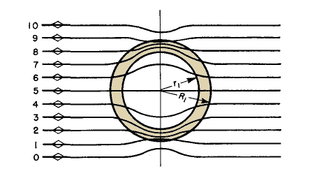
Magnetic shielding is ordinarily accomplished by a thick wall of ferrous metal or a series of thin, nesting boxes of high permeability material encasing the windings and core of the input transformer. Neither type of shield is applied to the power transformer because the flux lines originate at the power transformer and fan out in all directions from it. A large percentage of the flux would strike the shield at right angles and pass through it. On the other hand, the stray field near the input transformer is relatively uniform, and very few flux lines strike the shield at right angles. Thus more flux is bypassed by it. The action of a thick shield in keeping stray flux out of its interior is roughly illustrated in Fig. 153.
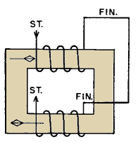
Multiple shields increase the action just mentioned because eddy currents induced in the shields set up fluxes opposing the stray field. Sometimes alternate layers of copper and magnetic material are used for this purpose, when hum pick-up 50 or 60 db below the no-shield value is required.(1) In core-type transformers the flux normally is in opposite directions in the two core legs, as shown in Fig. 154.
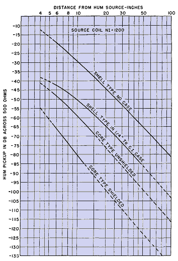
A uniform external field, however, travels in the same direction in both legs, and induced voltages caused by it cancel each other in the two coils. The relative effectiveness of these expedients is shown in Fig. 155.
Hum pick-up is given in decibels with zero decibel equal to 1.7 volts across 500 ohms, and distance from a typical small power transformer as abscissas. All curves are for 500-ohm windings working into their proper impedances, and with no orientation for minimizing hum. Using impedances much less than 500 ohms reduces the hum picked up. Orientation of coil position also reduces hum. For all types of units there is a position of minimum hum. With the unshielded shell type the angle between the transformer coil and the field is almost 90° and is extremely critical. With shielding, this angle is less critical, but the minimum amount of hum picked up in this position is not noticeably reduced. The core type is less critical, especially with a shield. The minimum amount of hum picked up is from 10 to 20 db less than the shielded shell type in its minimum position. Removing the shields from the core type may change its position of minimum pick-up. This is because the shields reduce hum by a process different from that of the two bucking coils. It is advantageous to have power transformers of the core type. Leakage fluxes from like coils on the two legs approximately cancel at a distant point. The U-and-I shape of lamination is better than the L shape because of its symmetry. A type C core has the advantage that gaps are inside the coils. Thus fringing is reduced, and stray flux from the core gap is minimized. Static shielding does not prevent normal voltage on a primary winding from being transferred inductively into a secondary winding. It is effective only against voltage transfer by interwinding capacitance. High-frequency currents from vacuum tube circuits are thus prevented from flowing back into the 60-cycle power circuits via filament and plate transformers. Without shielding, such currents may interfere with operation of nearby receivers. Likewise, voltages to ground on telephone lines are kept from interfering with normal voice frequency voltages between lines. The extent of static shielding depends upon the amount of discrimination required. Usually a single, thin, grounded strip of metal between windings is sufficient, with ends insulated to prevent a short circuit. Magnetic flux in the interwinding space causes eddy currents to flow in such shields, and even shields with insulated ends indicate a partial short circuit on test. This effect reduces the OCL of the transformer. If volts per layer are small compared to total winding voltage, a layer of wire is an effective shield. The start turn is grounded and the finish left free, or vice versa. A wire shield has none of the short-circuit effect of a wide strip shield. Usually a transformer that requires static shielding has a low-voltage winding; the shield can be placed close to this winding, needs little additional insulation, and occupies but a small fraction of the total coil space. If shields are placed between high-voltage windings, as in modulation transformers, the shields must be insulated from each winding with thick insulation. This materially increases the coil mean turn length, transformer size, and difficulty in obtaining good high-frequency response. Shields have questionable value in such transformers and usually are omitted.
|
||||||||||||
Home  Amplifier Circuits Amplifier Circuits  Shielding Shielding |
||||||||||||
Last Update: 2011-02-17


