| Electronic Transformers and Circuits is a free introductory textbook on transformers and related circuits. See the editorial for more information.... |

|

Home  Electronic Control Transformers Electronic Control Transformers  Peaking Transformers Peaking Transformers |
||||||||||


|
||||||||||
Peaking Transformers
It is stated in Electronic Control Circuits that a large angle of intersection between the grid firing voltage wave and critical grid voltage is desirable for accurate control. A grid wave form with vertical front edge would be ideal. To produce a steep peaked wave form for firing thyratron tubes, sometimes special transformers are used. Usually the design depends on the non-linearity of the magnetizing current.
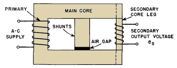
Figure 192 shows a peaking transformer in which the magnetic core is made of special laminations. The primary is wound on the full-width left leg, and the secondary on the right leg which is made of a few laminations of small width. In the space between primary and secondary is a laminated shunt path with an air gap.
Because of the shorter time for the change in Φs, dΦ/dt would remain nearly constant over the angle ΦS if there were no leakage flux, and for 1:1 turns ratio there would be approximately equal volts in the primary and secondary coils. The secondary flux change takes place over a much shorter period of time, and the flux rises to only a fraction of its maximum value Φm. Therefore less core area is needed in the secondary leg to obtain the desired voltage es. This leads to the following approximate ratio.
where AS = core area in the secondary legPeaked secondary voltage may be made steeper by the use of nickel-iron laminations in the secondary leg, because these alloys have sharp saturation. The air gap in the center leg prevents it from shunting all the primary flux, which would reduce the secondary voltage to zero. This air gap should be no more than 5 to 10 per cent of the window height, to keep leakage flux from threading through the secondary coil and giving a less peaked wave form. With this length of air gap and a total window length of twice the window height, the secondary turns are, for a 1:1 voltage ratio,
where NP is the number of primary turns.Transformers may be made to peak by the use of special circuits instead of special cores. Voltage wave forms like Fig. 193 are obtainable if the primary winding is operated at a voltage exceeding saturation but is connected in series with a large linear inductance or other high impedance. Grain-oriented core material, with its rectangular hysteresis loop, is well suited to peaking transformers. When primary and secondary windings are wound over the same magnetic path, the same volts per turn are induced in both windings, and equation 110 no longer applies. A peaking reactor circuit is shown in Fig. 262.
|
||||||||||
Home  Electronic Control Transformers Electronic Control Transformers  Peaking Transformers Peaking Transformers |
||||||||||
Last Update: 2011-01-24


