| Electronic Transformers and Circuits is a free introductory textbook on transformers and related circuits. See the editorial for more information.... |

|

Home  Magnetic Amplifiers Magnetic Amplifiers  Hysteresis Loops and Transfer Curves Hysteresis Loops and Transfer Curves |
||||||||||||||||||||||||


|
||||||||||||||||||||||||
Hysteresis Loops and Transfer Curves
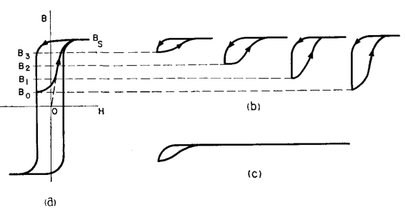
In a rectangular hysteresis loop material with B-H loop shown in Fig. 215 (a), the path traced over a flux excursion B0BS is more irregular in shape but still follows the left-hand trace of the loop. If magnetic amplifier cores are biased to a series of reset flux positions B0 to B3 the corresponding flux excursions and minor loops are those shown in Fig. 215(b). Usually, the load current far exceeds the control current necessary to reset the cores, so that these loops actually have a much longer region over which the loop width is practically zero, as shown in Fig. 215 (c). This is true of all the loops regardless of flux excursion. The foregoing is true of a slowly varying flux excursion, so that the locus of the lower end points of the minor loops is the left-hand trace of the d-c hysteresis loop. Most magnetic materials, including rectangular loop materials, have a wider loop when the hysteresis loop is taken under a-c conditions, because of eddy currents. The difference between loops is as shown in Fig. 216.
The locus of the end points of the minor loops under a-c flux excursions is neither the a-c nor the d-c loop but an intermediate line such as that drawn dot-dash in Fig. 216. The slope of this line is less than that of either the a-c or the d-c loop, and the gain of the magnetic amplifier is accordingly reduced. An analysis for the self-saturated magnetic amplifier of Fig. 214(a) is given below. Load current is assumed to have the same shape as eL in Fig. 214(b), and the following assumptions are made:
Θ1 = firing angle as in Fig. 214(b). Under the assumptions, equation 1 becomes
Integrating equation 114 gives
and
During the interval Θ1 < ωt < π, load voltage is
where RL is the load resistance. This may be integrated to give
Combining equations 116 and 118 and substituting equation 113,
The left side of equation 119 is the average load current over the conducting interval π/ω - t1. Average load current over the whole cycle is
Equation 120 has two flux terms: Φs, which is a fixed quantity for a given core material; and Φ0. The relation between Φ0 and control current is, as indicated in Fig. 215, the return trace of the major hysteresis loop. Thus equation 120 states that the average load current is the sum of a constant term and a term which has the same shape as the return trace of the hysteresis loop. Quantitatively, a self-saturated half-wave magnetic amplifier has a current transfer curve the same as the return trace of the core hysteresis loop, except that ordinates are multiplied by fAcN/108RL and are displaced vertically by an amount fBsAcN/108RL. Comparison with equation 113 reveals that the ordinate multiplier and vertical displacement are E/4,44RLBS and E/4,44RL, respectively. As noted above, the return trace should be modified to mean the dot-dash line of Fig. 216.
|
||||||||||||||||||||||||
Home  Magnetic Amplifiers Magnetic Amplifiers  Hysteresis Loops and Transfer Curves Hysteresis Loops and Transfer Curves |
||||||||||||||||||||||||
Last Update: 2011-02-17


