| Electronic Transformers and Circuits is a free introductory textbook on transformers and related circuits. See the editorial for more information.... |

|

Home  Magnetic Amplifiers Magnetic Amplifiers  Magnetic Amplifier Design Magnetic Amplifier Design |
||||||||||||||


|
||||||||||||||
Magnetic Amplifier Design
Of first concern in design is the reactor core material. Supermalloy or other high-percentage nickel alloys are best suited as core material for the low power input stage. Grain-oriented nickel steel is used in the stages where output power is appreciable, and grain-oriented silicon steel where power is large.
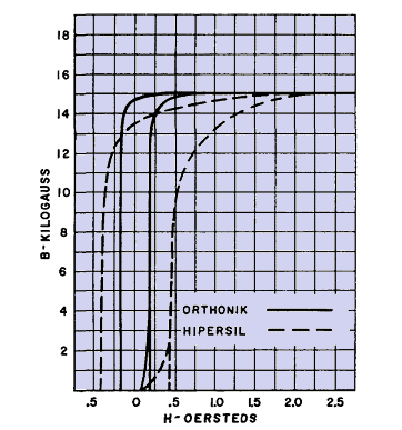
In either type of core there is a small inevitable air gap. In a toroid, the flux must change from one lamination to the next as it flows around the core. If the insulating space between laminations is 0.0005 in. and the average core length is 5 in., the effective core gap is 0.0005/5 = 0.0001 in. This gap is not negligible in high-permeability core material, but it is about one-tenth of the gap that manufacturers allow in type C cores. Effective core gap requires more control NI/in. and reduces gain because the gap causes a more sloping B-H loop. See Fig. 242. Special U-shaped punchings of grain-oriented steel are sometimes used with alternate stacking to reduce the effective core gap. Another effect that reduces gain is rectifier "back" resistance, or current flow during the part of the negative half-cycle when inverse voltage exists across the diode. The peak value of inverse voltage divided by the corresponding reverse current is the rectifier back resistance. For a given peak source voltage √2 E, the inverse peak rectifier voltage is 2 √ 2 E in the center-tap d-c circuit, and it is √2 E in the bridge circuit, for zero winding and rectifier forward IR drops. In a doubler amplifier with zero forward drop, inverse peak voltage is zero, and increases with forward drop up to a maximum of √2 E. The reverse current corresponding to these voltages resets the core more than control circuit current with no rectifier reverse current. This causes transfer characteristic slope to decrease; the unity ordinate of the normalized transfer curve is displaced to the right by the ratio of reverse current to cut-off control current Ic. Normal cut-off control current IC. and cut-off output current IN are not affected, because IC operates to reduce load current during the positive half-cycle. Good-quality rectifiers are as important as good core material. This applies equally well to leakage current and forward current IR drop. Losses may limit output in rectifiers as well as in reactors. Most of the I2R loss in windings of self-saturated amplifiers is usually in the load windings. This loss occurs during the part of the cycle in which load current flows, or while the core is saturated and core loss is zero. I2R loss is a maximum when Θ1 = 0 in Fig. 214(b). When Θ1 = 180°, I2R loss is negligible and core loss is a maximum. When the supply frequency is high, choice of rectifiers is limited to those with good high-frequency properties. At radio frequencies this may mean that suitable rectifiers are not available; simple magnetic amplifiers must then be used. To reduce core loss at high frequencies, ferrites are used. Insulation of toroidal coils is difficult to apply. Insulation between concentric windings is taped in and out like the wire. If voltage is low, the wire enamel is sufficient insulation. For 115- or 230-volt circuits, windings are laid on the core progressively, that is, with turns bunched so that adjacent turns have but a small a-c voltage difference. Insulation difficulties increase with voltage, and high-voltage reactors are preferably layer wound, with type C or stacked cores. Induced voltage in control windings requires careful attention, especially when control current is limited and many control turns are required. Although fundamental a-c voltage cancels in the control circuit, the full magnitude of this voltage is induced in the control windings. In the example of simple magnetic amplifier given in Section 111, the voltage induced in the control windings is 2,500/65 · 100 = 3,850 volts. With layer-wound coils and solventless resin coil impregnation the insulation is readily provided, but it would be difficult with toroidal coils. Winding space in a toroid is limited by the minimum practicable hole size in the finished coil. This varies with the kind of winding machine and also with the size of toroid. If d1 = hole diameterthen
On the outside of the toroid, the winding builds to a smaller height than on the inside. Since Aw is fixed by the minimum hole size, the coil outside diameter is
where Aw1 is area occupied by first winding. Equation 127 is approximate because wire turns tend to become circular after several layers are wound on the core.
|
||||||||||||||
Home  Magnetic Amplifiers Magnetic Amplifiers  Magnetic Amplifier Design Magnetic Amplifier Design |
||||||||||||||
Last Update: 2011-01-24


