Half-Wave Control of Magnetic Amplifiers
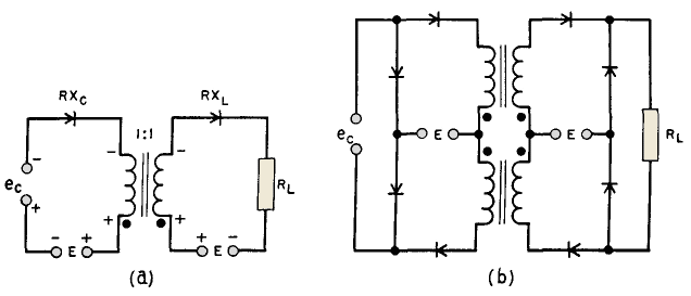
Through attention to a-c voltages present in the control circuit, Dr. R. A. Ramcy analyzes magnetic amplifiers in a manner which gives rise to new circuits with desirable properties.(1) A half-wave building block of such circuits is shown in Fig. 221 (a) for a 1:1 turns ratio reactor.
 |
| Fig. 221. Half-wave controlled magnetic amplifiers. |
The load circuit is the same as in the half-wave amplifier of Fig. 214. The control circuit comprises a-c voltage E and rectifier RXC in addition to variable rectified control voltage ec of polarity indicated. A-c voltage polarities are for the positive or conducting half-cycle in the load circuit. During this half-cycle, RXC blocks and the control voltage is zero. During the next half-cycle, a-c line voltage E - eC appears across the reactor control coil. If ec is zero, the core is not magnetized by control current flowing during the positive half-cycle, and the core is completely reset by E during the negative half-cycle. If the peak value of ec is equal to √2 E, it appears across the reactor in opposite phase to the line voltage and completely cancels it during the resetting half-cycle.
 |
| Fig. 222. Resetting voltages with half-wave control. |
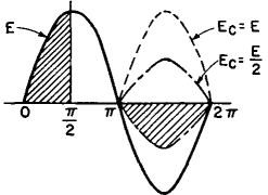
This is shown dotted in Fig. 222, with both voltage waves designated by capital letters. This cancellation results in zero resetting; therefore full output current flows over 180° of the positive half-cycle. If Ec = E/2 it subtracts from E, resulting in the lower dot-dash line of Fig. 222. The area under E - Ec (shown hatched) is just half of the area under E and therefore equals the hatched area under E during the interval 0 to π/2 of the positive half-cycle. That is, the reactor absorbs voltage E during the interval 0 to π/2 and allows current to flow from π/2 to π. But this is half of full or maximum output. Thus the output current is:
zero for Ec = 0
1/2 max for Ec - E/2
max for Ec = E
Several advantages accrue from this type of control:
- Output is proportional to control voltage.
- Output depends only on control voltage and is independent of variations in line voltage or frequency.
- Time of response is short (2 cycles or less).
- Filtered d-c source of control power is not necessary.
Proportionality of output to input voltage is strictly true only for zero control circuit resistance or zero reactor exciting current. The lower the control circuit resistance and reactor exciting current, the more nearly is output proportional to input. Rectangular B-H loop core material is necessary for linearity. Control circuit resistance can be made small without causing slow response in this circuit. Exciting current and control circuit resistance give rise to load voltage output with zero control voltage. Raising control voltage ec restores linearity of output. With half-wave control, voltage gain is more important than power gain; voltage gain is approximately equal to turns ratio. Mixing is not so readily accomplished in half-wave control circuits. Figure 221 (b) shows how two half-wave sections are combined to form a full-wave bridge circuit with d-c output. This circuit differs from the circuit of Fig. 217(6) in that the control windings are isolated from each other by the control circuit rectifiers. Voltage E in the control circuit is an a-c bias voltage, and ec is rectified a-c signal voltage. Zero output voltage appears across RL with ec = 0. When ec is increased, full-wave rectified voltage appears across RL. The fundamental a-c component of this voltage is zero.
|


 Magnetic Amplifiers
  Half-Wave Control of Magnetic Amplifiers


 Magnetic Amplifiers
  Half-Wave Control of Magnetic Amplifiers


