| Capacitors, Magnetic Circuits, and Transformers is a free introductory textbook on the physics of capacitors, coils, and transformers. See the editorial for more information.... |

|
Home  Magnetic Circuits Magnetomotive Force, mmf Magnetic Circuits Magnetomotive Force, mmf |
|||||||||||||||||||||||
| See also: Induced EMFs | |||||||||||||||||||||||


|
  |
||||||||||||||||||||||
Magnetomotive Force, mmf
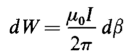
The unit of magnetomotive force is the ampere turn. It was shown in Chapter 2 that the energy required to move a unit test charge from one point to another in an electric field is equal to the voltage or electromotive force between those two points. This relationship is expressed mathematically by Eq. 2-10. An analogous situation exists for the magnetic field in that the energy required to move a unit magnet pole from one point to another along a certain path in the field is proportional to the magnetomotive force between these two points along the path taken by the unit pole. It should be carefully noted that the magnetic units of measurement are such that the magnetomotive force or mmf expressed in ampere turns is proportional (not equal) to the energy as is the case of the electromotive force in relation to the electric field. Furthermore, the energy required to transport a test charge from one point to another in an electric field is independent of the path along which the test charge is moved. This is another way of saying that the line integral of the electric field intensity between two points in the field is independent of the path over which it is integrated. However, the amount of energy expended in transporting a magnet pole from one point to another in a magnetic field depends upon the path traced by the magnet pole. This is another way of saying that the line integral of magnetic field intensity between two points in the magnetic field depends upon the path of integration. The magnetic field produced by a current in a long straight filament affords a good illustration of the effect of the path of integration in the magnetic field. Figure 3-7(a) shows the cross section of the filament (a cylindrical conductor) carrying an electric current away from the observer, i.e., into the page. Then, according to the right-hand rule, the direction of the magnetic field intensity resulting from this current is clockwise. Since the strength m of a unit pole is unity, the force required to hold a unit pole at a point where the magnetic field intensity is H can be evaluated from Eqs. 3-19 and 3-22. This force is found to be
The differential energy required to move the unit magnet pole against this force F through a differential distance ds is given by the following scalar product or dot product
or simply from Fig, 3-7(a) by
but
When Eq. 3-29 is substituted in Eq. 3-27 the result is
The magnetic field intensity H at a point well away from the ends of a long straight filament and produced by the current in the filament is expressed by Eq. 3-13 which, upon substitution in Eq. 3-30, yields
where I is the current in the filament expressed in amperes.
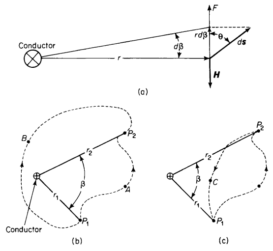
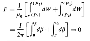
If in Fig. 3-7(b) the unit magnet pole is carried from P1 to P2 along the path through A, the energy expended in carrying the pole from P1 to P2 is determined by integrating as follows
The magnetomotive force expressed in ampere turns is the energy divided by the permeability μ0, thus
If on the other hand the unit magnet pole is carried from P1 to P2 in Fig. 3-7(b) along the path through B, the magnetomotive force expressed in amperes turns is evaluated as follows
For values of β other than π the magnitudes of FA and FB are unequal, but regardless of the value β, the signs of FA and FB will be opposite although the integration was carried out by progressing from P1 to P2 in both cases. Suppose that the unit magnet pole is carried completely around the conductor along a closed path in a counterclockwise direction starting at Pt following the path through A to P2 then through B back to P1. Then we have
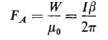
Equation 3-32 shows that energy is required to carry a magnet pole around a closed path that links a current and that the energy is proportional to the current. If the magnet is carried against the direction of the magnetic field intensity the mechanical energy applied to the magnet pole is positive, and if carried in the direction of the magnetic field intensity the energy applied to the magnet pole is negative. Equation 2-16 shows that the energy expended in carrying an electric charge around a closed path in an electric field is always zero. This characterizes a conservative field. The magnetic field is nonconservative since the magnetic pole takes on energy each time it is carried around a closed path that links a current. If the unit magnet pole is carried around the closed path [Fig. 3-7(c)] that does not link the current-carrying wire, i.e., from P1 through A to P2 and back through C to P1 the mmf and the energy are found to be zero as follows
In Eq. 3-33, integral P1 and P2 are shown in parentheses because they are not limits of integration but are merely the end points of the paths of integration. Although the integrations in Eqs. 3-32 and 3-33 are both taken around closed paths they do not lead to the same result. Equation 3-32 yields the current in the wire and Eq. 3-33 results in a value of zero.
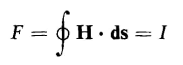
The relationship expressed in Eq. 3-32 is very useful and is more commonly given in terms of the magnetic field intensity H and can be derived directly from Eq. 3-27 with the following result
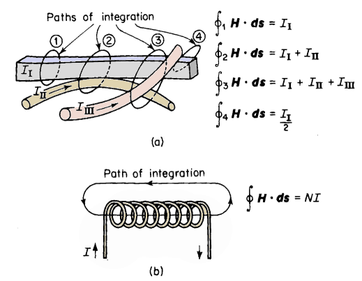
where I is the current linking the closed path of integration. When the closed path of integration is not linked by any current, as shown in Fig. 3-7(c), the value of the line integral H Although Eq. 3-34 was obtained for a closed path that links a straight conductor, it is valid for any closed path linking one or more conductors of any configuration or even part of a conductor. This equation is considered a general law sometimes called Ampere's circuital law. Paths of integration and the corresponding values of line integrals of H are shown in Fig. 3-8(a) and (b). In Fig. 3-8(a) path 4 links only one-half of the current in the rectangular conductor, path 1 links all the current in the rectangular conductor without linking any part of the round conductors, and path 3 links all three conductors in Fig. 3-8(a).
|
|||||||||||||||||||||||
| Home Magnetic Circuits Magnetomotive Force, mmf |
|
||||||||||||||||||||||


 ds is zero.
Last Update: 2011-01-11