| Capacitors, Magnetic Circuits, and Transformers is a free introductory textbook on the physics of capacitors, coils, and transformers. See the editorial for more information.... |

|

Home  Magnetic Circuits Magnetic Circuits  Flux Linkages Flux Linkages |
|||||||


|
|||||||
Flux Linkages
It was stated in Section 3-3 that magnetic lines of flux close upon themselves. As a result it is possible for magnetic flux lines to link electric circuits in much the same manner as flux lines link the windings on the cores in Figs. 3-16 and 3-17 and the manner in which the flux in the toroid of Fig. 3-9(a) links the turns in the winding. Another example of flux linking a circuit is the turn shown in Fig. 3-9(b). In the case of a winding having N turns and the same value of flux Φ links all the turns, the flux linkages are expressed by
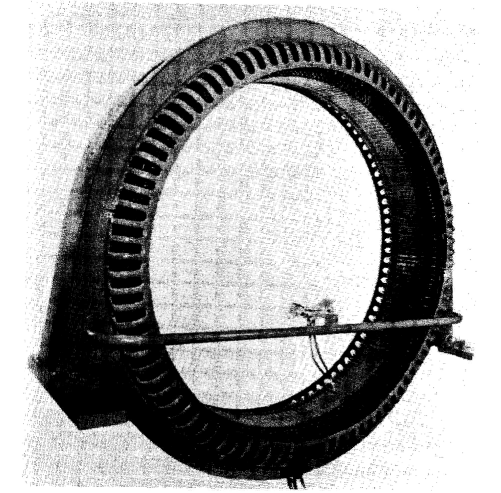
There are many cases, however, in which the different turns of a winding serve to link different amounts of flux. Electric motors and generators usually have windings in which the turns are distributed among slots, an arrangement which makes for differing amounts of flux linking the turns. Figure 3-24 shows the stator of a 3-phase synchronous motor. The coil ends of the stator winding are visible on the right-hand side of Fig. 3-24. Consider a winding in which the fluxes Φ1, Φ2, Φ3,... Φn link N1 N2 N3....,Nn turns respectively where N1 N2, N3, etc. may each be one or more turns, then from Eq. 3-54 we have
and the total flux linkages will be
or
|
|||||||
Home  Magnetic Circuits Magnetic Circuits  Flux Linkages Flux Linkages |
|||||||
Last Update: 2011-08-01


