| Capacitors, Magnetic Circuits, and Transformers is a free introductory textbook on the physics of capacitors, coils, and transformers. See the editorial for more information.... |

|
Home  The Transformer The Two-Winding Transformer The Transformer The Two-Winding Transformer |
|||||||


|
  |
||||||
The Two-Winding Transformer
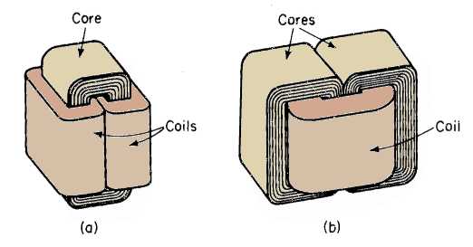
The two-winding transformer is one in which two windings are linked by a common time-varying magnetic flux. One of these windings, known as the primary, receives power at a given voltage from a source; the other winding, known as the secondary, delivers power, usually at a value of voltage different from that of the source, to the load. The roles of the primary and secondary windings can be interchanged. However, in iron-core transformers a given winding must operate at a voltage that does not exceed its rated value at rated frequency - otherwise the exciting current becomes excessive. Transformers that operate in the audio-frequency range generally have iron cores of a basic construction similar to those of the reactors and electromagnets discussed in Chapters 3 and 4. Figures 6-2(a) and 6-2(b) show the arrangement of cores and coils in transformers with wound cores. These cores are each wound of a long continuous strip of sheet steel in the direction in which the metal was rolled during manufacturing. In these transformers, the core is magnetized in the direction of rolling, thus making for lower core loss and lower exciting current than when the magnetization is in a direction across that of rolling. The wound core feature does not lend itself to the construction of large power transformers; also, in the case of small audio transformers, it is more economical to build the core out of laminations in the form of punchings. A conventional type of transformer is shown in Fig. 6-3.
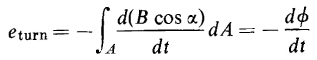
The windings of transformers are generally of copper, which, in small transformers, is round wire. In larger transformers, the copper is a ribbon, making for better utilization of space. However, aluminum is coming into use for transformer windings also, particularly in the low-voltage windings of distribution transformers. The conductor is in the form of a sheet of foil in which the ratio of width to thickness is usually 100:1 or larger. In most conventional iron-core transformers the core provides the main path for the magnetic flux, although some flux, known as leakage flux, leaks through the space between the windings, between the core and windings, and through some of the turns in one winding without linking the other winding. At no load, and under steady conditions, practically all of the flux is confined to the core of iron-core transformers and the leakage flux is usually negligible. Hence, the only appreciable flux that can link each of the turns in the windings at no load must be the flux in the core even if the turns are not wound tightly around the core, and even if the planes of the turns are not exactly at right angles to the flux. Therefore, at no load, the integral on the right-hand side of Eq. 6-4, which expresses the flux linking each turn, can yield only the value of the flux Φ in the core itself, except for the negligible no-load leakage flux. Therefore, the no-load voltage induced in each turn of the windings, according to Eq. 6-7, is
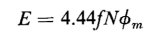
where Φ is the flux in the core. The rms value of the voltage induced in an N-turn winding by a sinusoidally time-varying flux of amplitude Φm is given by Eq. 5-19 as
This is sometimes called the transformer voltage formula. It can be extended, with suitable modifications, to the analysis of devices other than reactors and transformers, such as motors and generators.
|
|||||||
| Home The Transformer The Two-Winding Transformer |
|
||||||

Last Update: 2011-02-16