| Radio Antenna Engineering is a free introductory textbook on radio antennas and their applications. See the editorial for more information.... |

|
Home  Low-Frequency Antennas Vertical Antenna Low-Frequency Antennas Vertical Antenna |
||


|
  |
|
|
Vertical AntennaAuthor: Edmund A. Laport
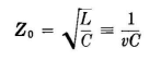
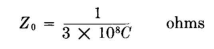
A vertical antenna is not a transmission line in the purest sense because its constants vary with distance from ground and the time of propagation of the fields from real and image charges is not small with respect to one period of the emitted wave. From a practical standpoint, however, these deviations from theoretical ideals are of small consequence. The concept of the characteristic impedance of an electrically long wire, vertical or otherwise, is of great practical convenience because it permits us to refer circuit conditions in an antenna to those so well known for transmission lines. To use the characteristic impedance quantitatively, however, we must be content with approximate values. The error, in most cases, is fortunately within that of the many other empirical factors with which one must deal in engineering. The characteristic impedance of a vertical antenna of any cross section can be calculated with suitable accuracy by considering a sample 1-meter unit of length at a height h above ground and the corresponding portion of its image. The characteristic impedance can then be obtained from electrostatics, using the theory of logarithmic potentials. A short discussion of this useful theory is given in Chap. 6. For a vertical antenna (a down lead or any vertical radiating portion of an antenna, whose diameter is small with respect to its length) a compromise value of Z0 for the entire vertical part can be calculated at the mid-height. The capacitance per meter C for the cross section used is computed from logarithmic-potential theory and the characteristic impedance calculated directly from the equation.
A vertical antenna with capacitive end loading in the form of a flat-top of any configuration can then be treated as a capacitively terminated transmission line of length Gν degrees and characteristic impedance Z0 (where Gν is the physical length of the vertical portion of the antenna in electrical degrees). The flat-top in turn can be treated as a transmission line or as several lines in parallel, and its approximate reactance can be calculated at the point of connection with the vertical, using Eq. (8), Chap. 4. These general facts can be used to calculate the fundamental frequency and the reactance of low-frequency antennas. The characteristic impedance of a horizontal wire or system of parallel wires can also be computed from logarithmic-potential theory within satisfactory limits of accuracy in certain simple cases. For example, the characteristic impedance of the horizontal portion of an inverted-L or a T antenna can be found by using the principles of electrostatics and the same equations one would use for transmission lines. The method is limited to single wires or to systems of parallel wires well removed from the fields of other parts of the antenna system. In the following section the application of such methods will be demonstrated. For suitable characteristic impedance formulas, consult Cases I, II and III, Chap. 4, as examples.
|
||
| Home Low-Frequency Antennas Vertical Antenna |
|
|
Last Update: 2011-03-19