| Transistor Basics is a free introductory textbook on transistors and their basic applications. See the editorial for more information.... |

|
Home  The Grounded Base Transistor Four-Terminal Analysis of Transistors Equivalent Passive 'T' Network The Grounded Base Transistor Four-Terminal Analysis of Transistors Equivalent Passive 'T' Network |
||||||||||


|
  |
|||||||||
|
Equivalent Passive 'T' NetworkAuthor: Leonard Krugman
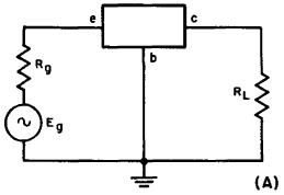
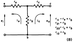
Fig. 3-7. (A) The basic circuit for transistor four-terminal network analysis. The simplest method of approaching the analysis of the equivalent transistor circuit is by an equivalent "T" network with no internal generating sources (passive basis). This circuit is illustrated in Fig. 3-7 (B). Under these conditions, the transistor parameters can be completely specified by the following terminal measurements:
Notice that the forward transfer resistance is equal to the backward transfer resistance. This is typical of a four-terminal passive network. In the practical case, then, it is only necessary to measure r12 or r21.
|
||||||||||
| Home The Grounded Base Transistor Four-Terminal Analysis of Transistors Equivalent Passive 'T' Network |
|
|||||||||
Last Update: 2011-01-30