| Capacitors, Magnetic Circuits, and Transformers is a free introductory textbook on the physics of capacitors, coils, and transformers. See the editorial for more information.... |

|
Home  The Transformer Equivalent Circuit of the Transformer Leakage Flux and Leakage Reactance The Transformer Equivalent Circuit of the Transformer Leakage Flux and Leakage Reactance |
|||||||||||||||||||||||||||||||||||||||


|
  |
||||||||||||||||||||||||||||||||||||||
Leakage Flux and Leakage Reactance
It was pointed out in Section 6-3 that in an actual iron-core transformer all the magnetic flux is not confined completely to the core, especially under load conditions, i.e., when the secondary is delivering appreciable current. Although Eqs. 6-7 and 6-8 could theoretically be made to take into account the mutual flux and the leakage fluxes to give the total induced emf in each
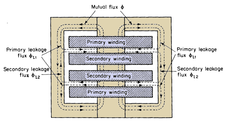
of the two windings, it is more convenient to divide the magnetic flux into three components. These are
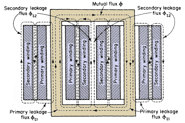
Although Figs. 6-4, 6-7, 6-8, and 6-9 represent iron-core transformers, the magnetic flux in air-core transformers can also be divided into the three components, namely, mutual flux and primary and secondary leakage fluxes, even though the air-core transformer does not have a discretely defined magnetic core. The arrangement of the windings shown schematically in Figs, 6-7(a) and 6-7(b) make for high magnetic leakage, since the leakage flux can spread out over a relatively large area. When the windings are arranged as shown in Figs. 6-8 and 6-9, the magnetic leakage is relatively small, since the leakage flux is restricted to paths of relatively small cross sections, and hence, of correspondingly high magnetic reluctance. Although Figs. 6-7, 6-8, and 6-9
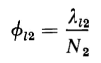
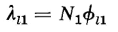
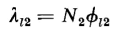
show separately defined paths for the three component fluxes, these fluxes do not exist as independent entities, but merge into a common flux pattern. Nevertheless, the concept of these three component fluxes facilitates the analysis of transformer performance. The actual flux paths are such that the leakage fluxes are distributed throughout the windings rather than concentrated into spaces between the windings. As a result, each winding is subjected to partial flux linkages. This means that differing amounts of leakage flux link the different turns of a given winding. Therefore, the leakage fluxes Φl1 and Φl2 are equivalent leakage fluxes; the former links all N1 turns of the primary and the latter links all N2 turns of the secondary. Thus, if λl1 = the primary leakage flux linkage, and λl2 = the secondary leakage flux linkage, then
and
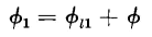
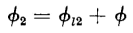
Furthermore, if Φ is the equivalent mutual flux linking all the turns of both windings, then the total equivalent fluxes linking the primary and the secondary windings, respectively, are
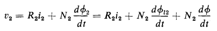
and the primary and secondary terminals voltages are
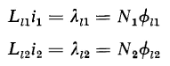
The primary leakage flux linkage and the secondary leakage flux linkage are
and from these the primary leakage inductance and secondary leakage inductance are, respectively
so that
and
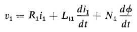
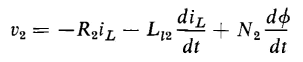
When Eqs. 6-39 and 6-40 are substituted in Eos. 6-33 and 6-34, the primary and secondary voltages are expressed by
Equation 6-42 can be rewritten in terms of iL on the basis of Eq. 6-15 to read
Since the leakage flux paths are largely in air, the leakage inductances Ll1 and Ll2 are practically constant. If a sinusoidal voltage, having an effective or rms value of V1 v, is applied to the primary of an air-core transformer when the secondary is connected to a linear load impedance, the primary current I1 and the secondary load current IL will also be sinusoidal. The quantities I1 and IL are the rms values of the primary current and secondary load current. It was mentioned in Chapter 5 that the exciting current in iron-core transformers contains harmonics, and is therefore not sinusoidal. The exciting current, however, is small enough in comparison with the rated primary current of the transformer so that its effect on the wave form of the primary and secondary currents is usually negligible in the normal range of load. Thus, if the impedance of the load in the secondary is linear, the primary and secondary currents in an iron-core transformer are practically sinusoidal for normal load conditions if the voltage applied to the primary is sinusoidal. Equations 6-41 and 6-43 can be rewritten in terms of phasor quantities as follows
where V1 = the effective applied primary terminal voltage
|
|||||||||||||||||||||||||||||||||||||||
| Home The Transformer Equivalent Circuit of the Transformer Leakage Flux and Leakage Reactance |
|
||||||||||||||||||||||||||||||||||||||


Last Update: 2011-02-16